
Magnetic resonance scanner and antenna

a magnetic resonance scanner and antenna technology, applied in the field of magnetic resonance scanners, can solve the problems of structure-borne noise excitation of the natural frequencies of the examination object, perturbation of the antenna system, etc., and achieve the effect of rapid adaptation of the adjustment device and contribution to the mechanical stability of the antenna system

Active Publication Date: 2018-12-25
SIEMENS HEALTHCARE GMBH
View PDF10 Cites 0 Cited by
  • Summary
  • Abstract
  • Description
  • Claims
  • Application Information

AI Technical Summary

Benefits of technology

The present invention relates to an adjustable antenna system for medical applications, which allows for the controlled shifting of natural frequencies. The system includes a support element that carries an antenna element, and an adjustment device that can rapidly adapt to different requirements. The adjustment device can induce a mechanical stress on the support element to shift natural frequencies, and it is formed to minimize energy transmission and to increase patient comfort. The system offers several possibilities for minimizing energy transmission and can simultaneously find an advantageous setting with respect to patient comfort.

Problems solved by technology

Oscillations of the antenna system are perturbing, in particular, when the oscillations cause interactions in a frequency range critical for the imaging or the patient comfort during operation of the magnetic resonance imaging system.
The excitation of the natural frequencies of the examination object may take place by structure-borne noise.

Method used


Image

  • Magnetic resonance scanner and antenna
  • Magnetic resonance scanner and antenna
  • Magnetic resonance scanner and antenna

Examples


Embodiment Construction

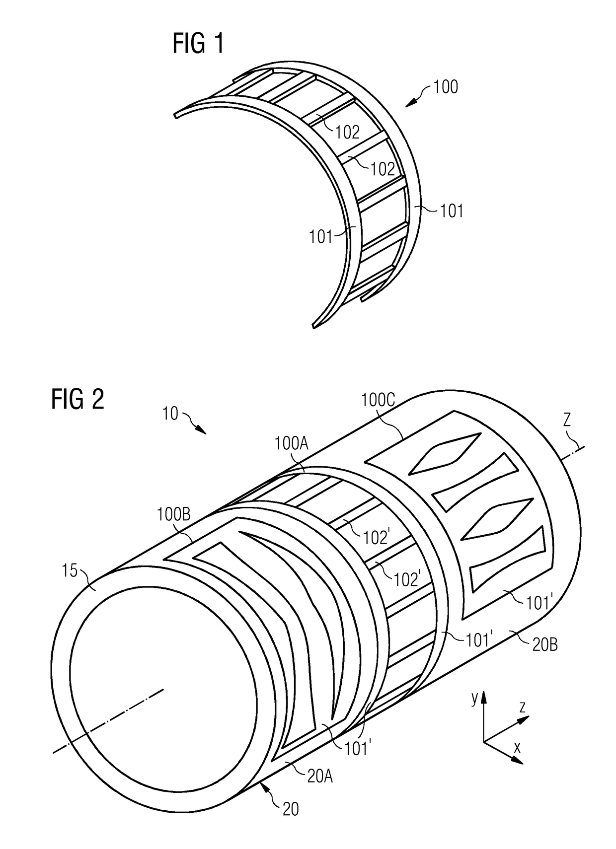
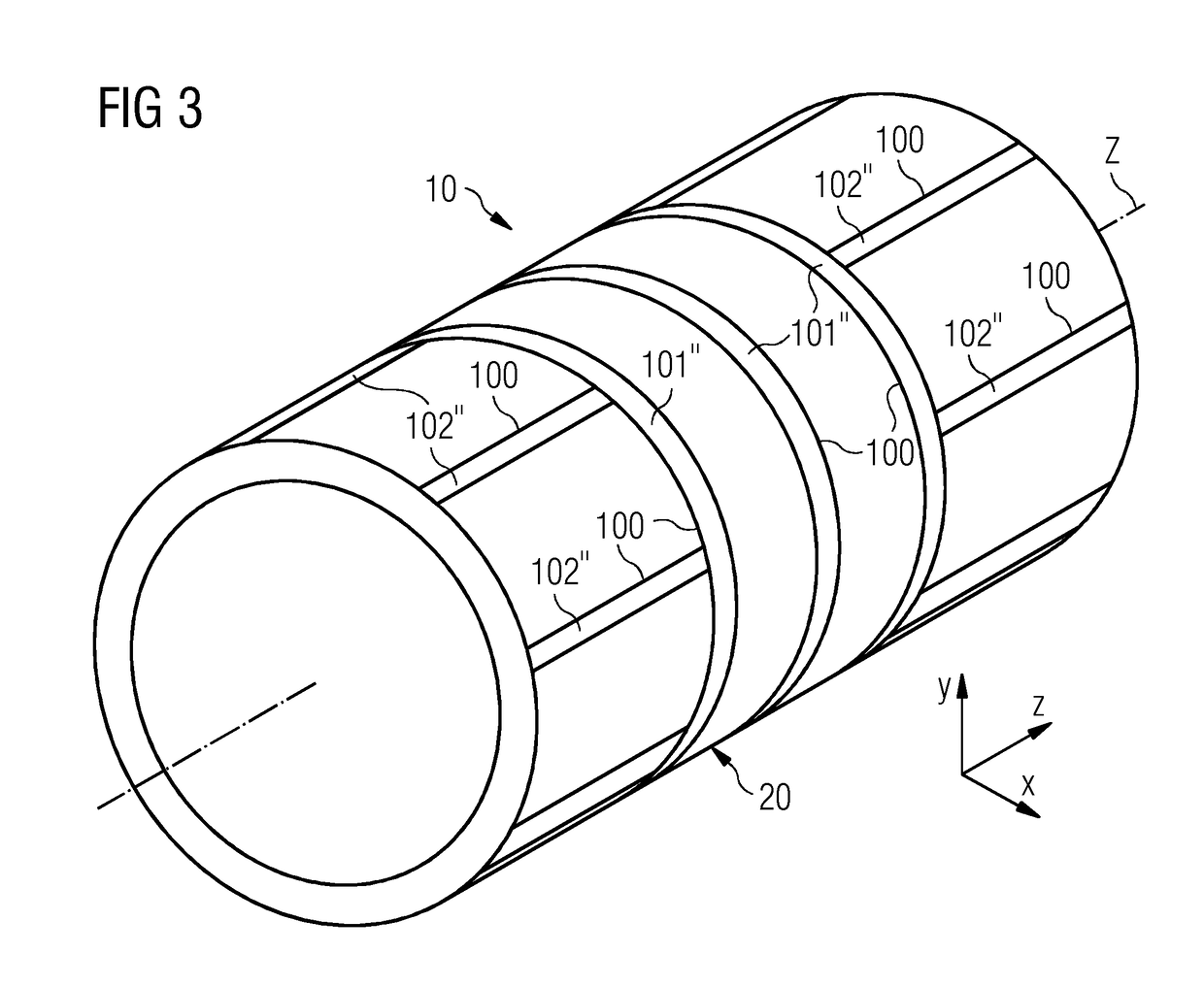
[0078]FIG. 1 depicts one embodiment of an adjustment device 100 that may be built into an antenna system. The adjustment device 100 is an arrangement of leaf springs, or rod springs, which include a plurality of leaf spring elements 101, 102, or spring elements.

[0079]Instead of the leaf spring elements 101, 102, it is also possible to use round rods or square rods. These spring elements may also be laminated in a composite structure, for example, wound tubes, and in particular the spring elements may be wound directly into a laminate, or a glass fabric (e.g., fully enclosed by the fabric of the glass structure, in particular a glass fiber fabric). The spring elements may also be cast into a glass fabric. The spring element may include or be a “bimetallic” element, (e.g., a combination of metals having different coefficients of thermal expansion), with which a force may actively be generated, for example, by local heating by a heating element.

[0080]The leaf spring elements 101, 102 a...


PUM


Abstract

The embodiments relate to a magnetic resonance scanner including an antenna system having an adjustment device for modifying the natural frequency of a natural mechanical oscillation mode of the antenna system. According to the embodiments, in a method for operating a magnetic resonance imaging system having a magnetic resonance scanner comprising an antenna system, a natural frequency of a natural mechanical oscillation mode of the antenna system is controlled and / or regulated.

Description

CROSS-REFERENCE TO RELATED APPLICATIONS[0001]This application claims the benefit of DE 10 2013 206 555.8, filed on Apr. 12, 2013, which is hereby incorporated by reference in its entirety.TECHNICAL FIELD[0002]The embodiments relate to a magnetic resonance scanner having an antenna system, to a magnetic resonance imaging system having such a magnetic resonance scanner, to a method for operating a magnetic resonance imaging system, and to a method for setting a natural frequency of an antenna system of a magnetic resonance scanner.BACKGROUND[0003]Magnetic resonance tomography is a widespread method for obtaining images of the interior of a body. In this method, the body to be examined is exposed to a relatively strong base magnetic field, for example, with a strength of several tesla. A radiofrequency excitation signal (the so-called B1 field) is emitted using a suitable antenna system, the effect of which is to tilt the nuclear spins of particular atoms resonantly excited by this rad...

Claims


Application Information

Patent Timeline
Patent Type & Authority Patents(United States)
IPC IPC(8): G01R33/565G01R33/34
CPCG01R33/565G01R33/34G01R33/56509G01R33/34007G01R33/34046
Inventor LAZAR, RAZVANSCHRAMM, MARTIN
Owner SIEMENS HEALTHCARE GMBH
Learn More