
Illumination devices, and methods of fabricating same

a technology of illumination device and fabrication method, applied in the field of light emitters, can solve problems such as power loss

Active Publication Date: 2018-12-18
CREELED INC
View PDF188 Cites 5 Cited by
  • Summary
  • Abstract
  • Description
  • Claims
  • Application Information

AI Technical Summary

Benefits of technology

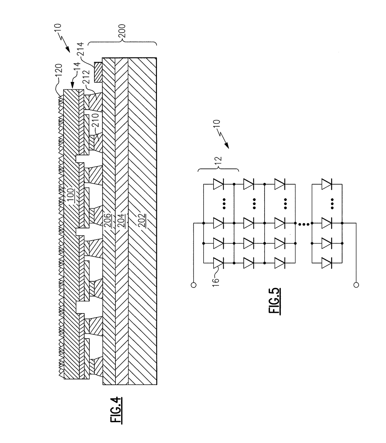
This approach enhances system performance by reducing resistive losses, improving driver efficiencies, and providing fault tolerance, allowing for more efficient power supply designs and increased system efficacy.

Problems solved by technology

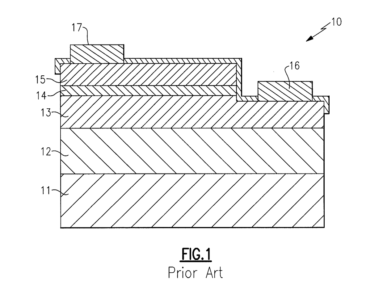
a) There is a fixed cost (power drops) that occurs in a driver assembly. These driver assemblies are made of “pn junctions” so that there is a power loss each time that a “junction” is added in the driver technology. Hence, the overhead (this fixed cost of power) can be amortized over each light emitting diode device, such that the cost of going to higher voltage strings and many light emitting diode devices is better than lower voltage strings and few parts.

Method used


Image

  • Illumination devices, and methods of fabricating same
  • Illumination devices, and methods of fabricating same
  • Illumination devices, and methods of fabricating same

Examples


Embodiment Construction

)

[0394]The present inventive subject matter now will be described more fully hereinafter with reference to the accompanying drawings, in which embodiments of the inventive subject matter are shown. However, this inventive subject matter should not be construed as limited to the embodiments set forth herein. Rather, these embodiments are provided so that this disclosure will be thorough and complete, and will fully convey the scope of the inventive subject matter to those skilled in the art. Like numbers refer to like elements throughout. As used herein the term “and / or” includes any and all combinations of one or more of the associated listed items.

[0395]The terminology used herein is for the purpose of describing particular embodiments only and is not intended to be limiting of the inventive subject matter. As used herein, the singular forms “a”, “an” and “the” are intended to include the plural forms as well, unless the context clearly indicates otherwise. It will be further under...


PUM


Abstract

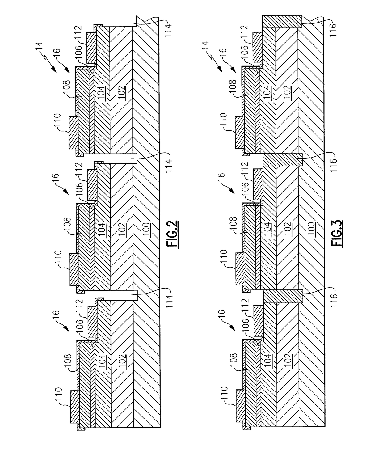
A light emitter, comprising a monolithic n-type layer (comprising at least first and second n-type regions), a monolithic p-type layer (comprising at least first and second p-type regions), at least a first isolation region and at least a first electrically conductive via that extends through at least part of the first isolation region. At least part of the first isolation region is between the first n-type region and the second n-type region, and / or least part of the first isolation region is between the first p-type region and the second p-type region.

Description

CROSS-REFERENCE TO RELATED APPLICATIONS[0001]This application is a continuation of U.S. patent application Ser. No. 12 / 017,600, filed Jan. 22, 2008 (now U.S. Patent Application Publication No. 2008 / 0211416), the entirety of which is incorporated herein by reference as if set forth in its entirety.[0002]This application claims the benefit of U.S. Provisional Patent Application No. 60 / 982,909, filed Oct. 26, 2007, the entirety of which is incorporated herein by reference.[0003]This application claims the benefit of U.S. Provisional Patent Application No. 60 / 986,795, filed Nov. 9, 2007, the entirety of which is incorporated herein by reference.[0004]This application claims the benefit of U.S. Provisional Patent Application No. 60 / 885,937, filed Jan. 22, 2007, the entirety of which is incorporated herein by reference.FIELD OF THE INVENTION(S)[0005]The present inventive subject matter relates to light emitters, systems incorporating such light emitters, and methods of making such light e...

Claims


Application Information

Patent Timeline
Patent Type & Authority Patents(United States)
IPC IPC(8): H01L25/075H05B33/08H01L33/38H01L33/04H01L33/32H01L21/265H01L33/62H01L27/15H01L33/44H05B44/00
CPCH01L25/0756H01L27/156H01L33/04H01L33/32H01L33/38H01L33/382H05B33/0803H01L2924/0002H01L21/2654H01L27/153H01L33/385H01L33/44H01L33/62H01L2924/00H05B45/37H05B45/30H05B45/38H01L33/145
Inventor NEGLEY, GERALD H.VAN DE VEN, ANTONY PAUL
Owner CREELED INC
Learn More