Systems and method for removal of acid gas in a circulating dry scrubber

a dry scrubber and acid gas technology, applied in the direction of separation process, grain treatment, dispersed particle separation, etc., can solve the problems of affecting the removal efficiency of acid gas,

Active Publication Date: 2018-12-18
MISSISSIPPI LIME CO
View PDF39 Cites 8 Cited by
  • Summary
  • Abstract
  • Description
  • Claims
  • Application Information

AI Technical Summary

Problems solved by technology

Flue gases are generally very complex chemical mixtures which comprise a number of different compositions in different percentages depending on the material being combusted, the type of combustion being performed, impurities present in the combustion process, and specifics of the flue design.
However, the release of certain chemicals into the atmosphere which commonly appear in flue gases is undesirable, and therefore their release is generally regulated by governments and controlled by those who perform the combustion.
The halogenated acids also contribute to corrosion of internal equipment or, uncaptured, pollute the air via stack emissions.
However, mitigation of the above undesirable compounds can be very difficult.
Because of the required throughput of a power generation facility, flue gases often move through the flue very fast and thus are present in the area of scrubbers for only a short period of time.
Further, many scrubbing materials often present their own problems.
Specifically, having too much of the scrubbing material could cause problems with the plant's operation from the scrubber material clogging other components or building up on moving parts.
Thus, high surface area does not itself warrant a prediction in improved removals of acid gases.

Method used


Image

  • Systems and method for removal of acid gas in a circulating dry scrubber
  • Systems and method for removal of acid gas in a circulating dry scrubber
  • Systems and method for removal of acid gas in a circulating dry scrubber

Examples


Embodiment Construction

)

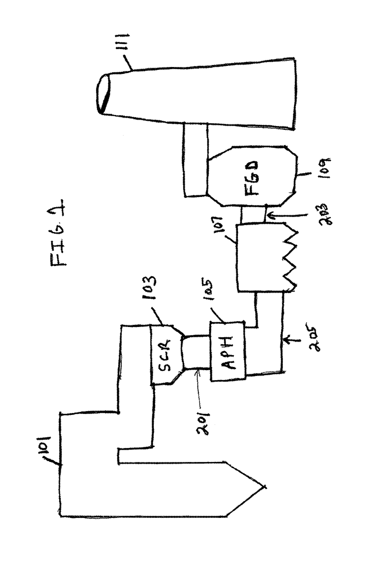
[0028]Most flue gas scrubbing systems are commonly focused on making sure that certain materials do not leave the flue stack and disperse in the air for environmental reasons. FIG. 1 shows a loose block diagram of an arrangement of a flue gas duct system such as can be used in a coal fired power plant. Generally, major components include the boiler (101), a selected catalytic reduction (SCR) system for reducing NOx emissions (103), an air preheater (APH) (105), a bag house or electrostatic precipitator (ESP) (107), a Flue Gas Desulfurization (FGD) unit (109), and then the exhaust stack (111).

[0029]Traditionally the FGD system (109) has utilized wet flue gas desulfurization (WFGD) which provides wet lime or limestone scrubbers where the calcium source (lime or limestone) is mixed in a slurry and introduced to the gas stream in a large reactor to “scrub” the SO2 from the gas stream. Most coals burned in these plants contain small concentrations of chlorine. The chlorine is readily sc...


PUM

PropertyMeasurementUnit
sizeaaaaaaaaaa
sizeaaaaaaaaaa
BET surface areaaaaaaaaaaa

Abstract

Systems and methods for the use of highly reactive hydrated lime (HRH) in circulating dry scrubbers (CDS) to remove sulfur dioxide (SO2) from the flue gas.

Description

CROSS REFERENCE TO RELATED APPLICATION(S)[0001]This application is a Continuation-in-Part (CIP) of U.S. Utility patent application Ser. No. 14 / 846,554, filed Sep. 4, 2015, which claims the benefit of U.S. Provisional Patent Application Ser. No. 62 / 046,696, filed Sep. 5, 2014. This application is also a Continuation-in-Part (CIP) of U.S. Utility patent application Ser. No. 15 / 344,173, filed Nov. 4, 2016, which is a Divisional of U.S. Utility patent application Ser. No. 13 / 594,538, filed Aug. 24, 2012, and now U.S. Pat. No. 9,517,471. The entire disclosure of all the above documents is herein incorporated by reference.BACKGROUND OF THE INVENTION1. Field of the Invention[0002]The invention relates generally to air pollution control processes aimed at controlling acid gases that are emitted from industrial, utility, incineration, or metallurgical process. Specifically the invention concerns the mitigation of Sulfur Dioxide (SO2), Hydrochloric acid (HCl), and Sulfur Trioxide (SO3) using ...

Claims


Application Information

Patent Timeline
Patent Type & Authority Patents(United States)
IPC IPC(8): B01D53/50B01D53/83B02C23/08C04B2/06C01F11/02C09C1/02B01D53/10B01D53/74
CPCB02C23/08B01D53/502B01D53/83C01F11/02C04B2/06C09C1/02B01D2253/306B01D53/10B01D53/74B01D2251/404B01D2251/604B01D2253/304C09C1/021B01D53/508B01D53/685B01D2258/0283C01F11/464C01F11/48
Inventor BIEHN, CURTISGRIFFARD, RANDYDEGENOVA, MARKVAN RENS, ERIC
Owner MISSISSIPPI LIME CO
Why Eureka
Try Eureka