Scaffolding coupler, standard and scaffolding system

a scaffolding and coupler technology, applied in the direction of scaffold connections, building scaffolds, building aids, etc., can solve the problems of large number of scaffolding, large amount of longitudinal ledgers required for erecting scaffolding, and large number of placement of scaffolding, so as to achieve a lower cost price

Active Publication Date: 2018-11-06
SCAFOM HLDG
View PDF11 Cites 3 Cited by
  • Summary
  • Abstract
  • Description
  • Claims
  • Application Information

AI Technical Summary

Benefits of technology

[0006]The invention contemplates a scaffolding coupler which, while maintaining the above described advantages of the known scaffolding coupler, remedies the above described disadvantages of the known scaffolding coupler at least in part. It should be noted that the above described disadvantages and problems have been recognized by the inventor and therefore do not form part of the state of the art. More particularly, the object of the invention is a scaffolding coupler which consists of fewer parts and hence can be manufactured at a lower cost price.
[0025]Such standards and such a scaffolding system, which can also be utilized with the scaffolding couplers that are shown and described in, for instance, WO2012 / 128630, offer the advantage that the scaffolding couplers of the transverse ledgers do not rest on the scaffolding couplers of the longitudinal ledgers or the other way around. Instead, the scaffolding couplers of the longitudinal ledgers have, in each ledger connecting zone, their own associated supporting projection on the standard and the scaffolding couplers of the transverse ledgers have, in each ledger connecting zone, their own associated supporting projection on the standard. Consequently, there is no need to place longitudinal ledgers which are not necessary from a viewpoint of strength and rigidity of the scaffolding, but which would only be placed to provide a supporting surface for the scaffolding couplers of the transverse ledgers. Erecting scaffolding can thus be realized faster and with fewer ledgers than with the scaffolding known from WO2012 / 128630.

Problems solved by technology

A drawback of the system described in WO2012 / 128630 resides in the couplers of transverse ledgers resting on the couplers of the longitudinal ledgers which in turn rest on a supporting projection, or the other way around.
In some cases, this leads to placement of a larger number of longitudinal ledgers than required from a viewpoint of strength and rigidity of the entire scaffolding.
The consequences are that it takes longer to erect the scaffolding and that a larger amount of longitudinal ledgers is required for erecting the scaffolding.
Both consequences lead to high costs of the scaffolding, which is undesired.
Due to the four parts and the mounting operations, the known scaffolding coupler is relatively expensive.
Another drawback of the known scaffolding coupler is that the wedge has to be struck into place at a first free end of the wedge and that the wedge can be knocked loose again from a diametrically opposed side of the ledger at a second free end of the wedge.
In some cases, when erecting and dismantling scaffolding, this is quite impractical as regularly, one of the free ends of the wedge is poorly accessible for a hammer, so that knocking the wedge loose can only be done with much effort.

Method used


Image

  • Scaffolding coupler, standard and scaffolding system
  • Scaffolding coupler, standard and scaffolding system
  • Scaffolding coupler, standard and scaffolding system

Examples


Embodiment Construction

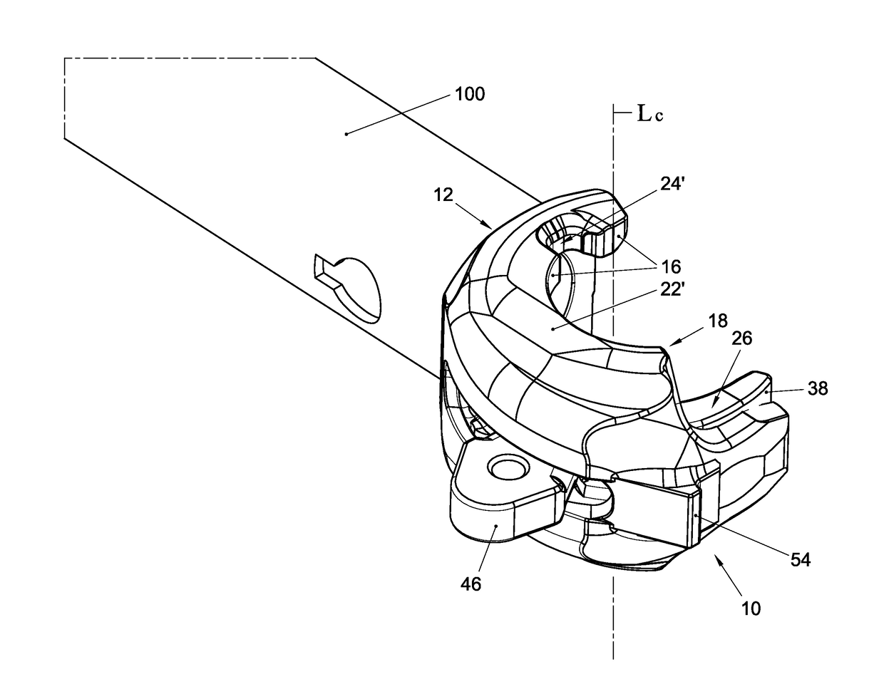
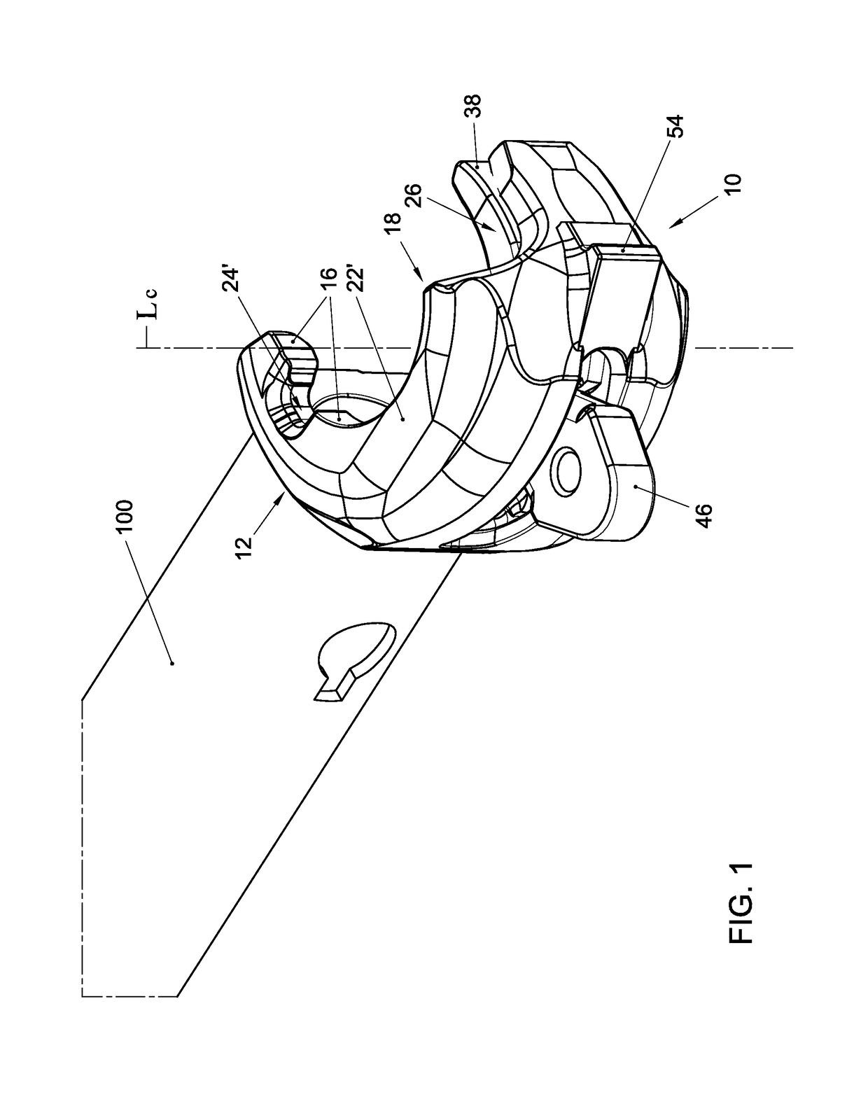
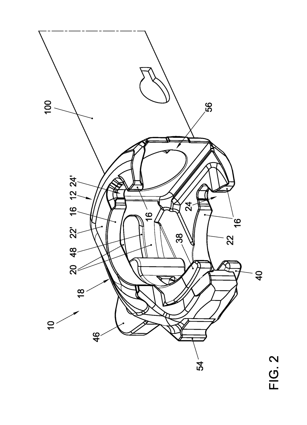
[0042]FIGS. 1-7 show an example of a scaffolding coupler in which various embodiments as described in the subclaims are embodied. It is noted that the embodiments can also be utilized independently of each other and that the invention is not limited to the example shown in the figures. In the following, various embodiments will be described, while, with the aid of reference numerals, reference is made to the figures. The reference numerals are herein used for clarification but have no limitative effect. An embodiment can also be configured in another manner than represented in the example shown in the figures.

[0043]In the most general terms, the invention provides a scaffolding coupler 10 intended for fixed connection to the ends of a ledger 100 of a scaffolding system, for instance by means of a welded joint. The scaffolding system comprises in any case ledgers 100 and standards 110. An example of an embodiment of a standard 110 is shown in FIG. 8. Each standard 110 comprises an el...


PUM


Abstract

A scaffolding coupler intended for fixed attachment to the ends of a ledger of a scaffolding system. The scaffolding coupler comprises a foot and a hook which is integrally connected with the foot. The hook has a radial inside contour which is substantially circular segmental. The scaffolding coupler has at least one supporting surface which is formed by the foot and the hook and which, with the scaffolding coupler connected to a standard, rests on a supporting projection of the respective standard. The scaffolding coupler further comprises a pin which is slideably connected to the hook. The pin is configured as a bent pin, having a substantially circular segmental inside contour, which, in use, abuts directly against a pipe wall of a standard to be coupled to the first ledger or a ledger. The bent pin has a substantially circular segmental outside contour which abuts against the substantially circular segmental inside contour of the hook.

Description

CROSS-REFERENCE TO RELATED APPLICATIONS[0001]This application is a U.S. National Stage application under 35 U.S.C. § 371 of International Application PCT / NL2015 / 050392 (published as WO 2015 / 187010 A1), filed Jun. 2, 2015, which claims the benefit of priority to NL 2012924, filed Jun. 2, 2014. Benefit of the filing date of each of these prior applications is hereby claimed. Each of these prior applications is hereby incorporated by reference in its entirety.FIELD[0002]The invention relates to a scaffolding coupler which is fixedly connected with the ends of a ledger and serves for coupling the ledger to a standard or to another ledger. The invention further relates to a standard and to a scaffolding system comprising standards and ledgers.BACKGROUND[0003]WO2012 / 128630 relates to a scaffolding system of the type where the standards comprise supporting projections which are formed through plastic deformation of the pipe wall of the standard. The ledgers comprise couplers with the aid o...

Claims


Application Information

Patent Timeline
Patent Type & Authority Patents(United States)
IPC IPC(8): E04G1/06E04G1/12E04G7/30E04G7/32
CPCE04G7/307E04G1/06E04G7/32E04G7/301E04G1/12
Inventor BRINKMANN, FRANCISCUS JOZEF LEONARDUS HUBERTUSKUUNDERS, GUUS FRANCISCUS JOHANNES
Owner SCAFOM HLDG
Why Eureka
Try Eureka