
Pedicle mountable retractor system

a retractor system and pedicle technology, applied in the field of medical devices, can solve the problems of difficult access to the anterior intervertebral space, too invasive procedures, and damage to spinal structures,

Active Publication Date: 2018-10-30
MINIMAL INVASIVE TECH PTY LTD
View PDF19 Cites 8 Cited by
  • Summary
  • Abstract
  • Description
  • Claims
  • Application Information

AI Technical Summary

Problems solved by technology

Firstly, it may be accessed through the abdomen, but this procedure may be too invasive.
In establishing access to the anterior inter-body space from posterior, damage may be caused to the spinal structures.
However, management of the posterior soft tissue and neural structures during this minimal invasive approach makes access to the anterior inter-vertebral space more challenging.
These devices and methods are unreliable and potentially dangerous, at least because they are susceptible to relative movement between the body of the patient and the anchor.
The known tubes are in excess of 100 mm in length, extend along the lines and they often interfere in space, which may lead to inaccurate placement of the pedicle screws.
Furthermore, the known assemblies comprise a cumbersome, complex and time consuming mechanism for releasing the tube from the pedicle screw.

Method used


Image

  • Pedicle mountable retractor system
  • Pedicle mountable retractor system
  • Pedicle mountable retractor system

Examples


Embodiment Construction

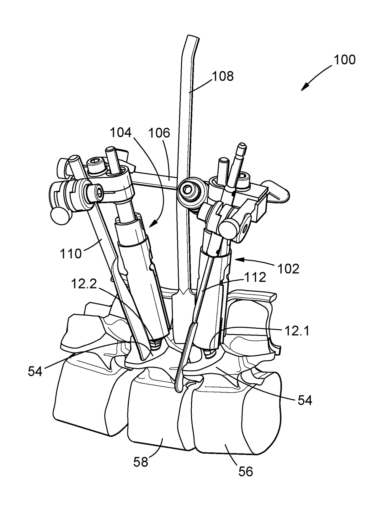
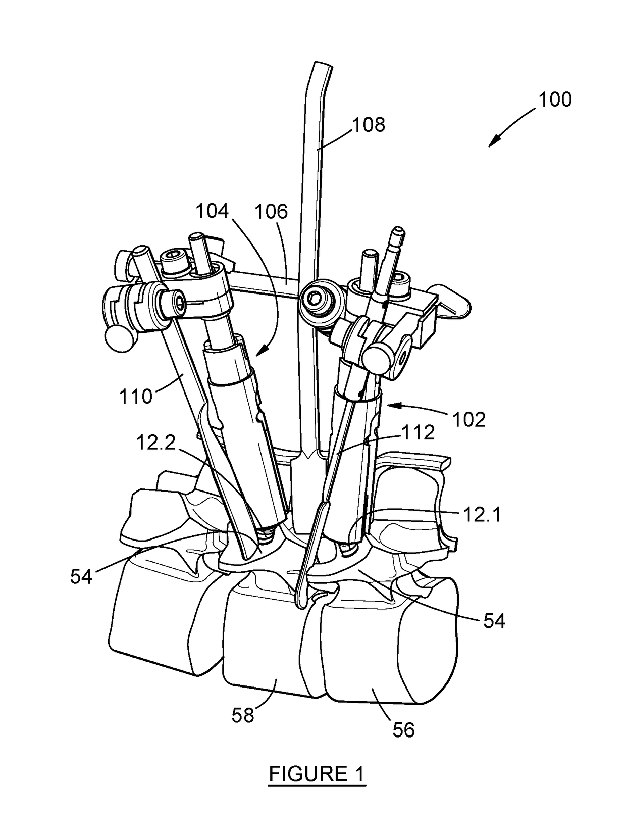
[0064]An example embodiment of a retractor system is generally designated by the reference numeral 100 in FIGS. 1, 9 and 10.

[0065]The retractor system 100 comprises a first tower 102 which is mountable on a first surgical screw, in the example embodiment in the form of a pedicle screw 12.1. A second tower 104 is mountable on a second pedicle screw 12.2. A link 106 extends between the first and second towers and at least a first elongate retractor element 108 is mountable on the link.

[0066]In the example embodiment, the first and second pedicle screws 12.1 and 12.2 are similar in configuration and the first and second towers 102 and 104 are also similar in configuration and therefore the first pedicle screw 12.1 and first tower 102 only will be described in more detail below.

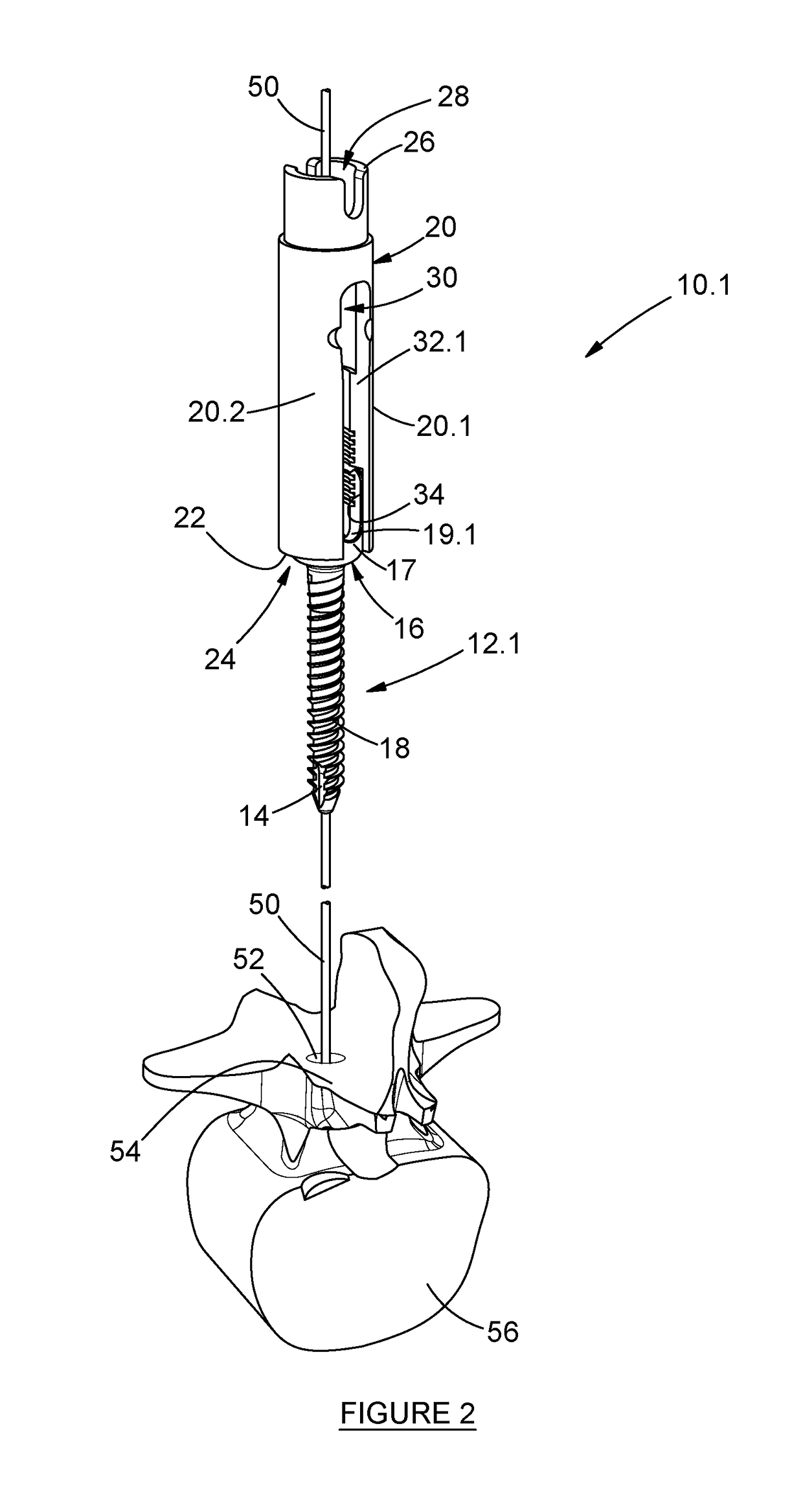
[0067]Referring to FIG. 2, the pedicle screw 12.1 forms part of a releasable assembly 10.1 comprising the pedicle screw and a first tube 20 of the first tower 102. The pedicle screw 12.1 defines an axial bore 14 ...


PUM


Abstract

A retractor system 100 comprises a first tower 102 which is mountable on a first surgical screw 12.1. A second tower 104 is mountable on a second surgical screw 12.2. A link 106 extends between the first and second towers. At least a first elongate retractor element 108 for at least one of muscle, tissue and nerve structures is movably mountable on the link.

Description

BACKGROUND[0001]Field of the Invention[0002]This application relates to a medical device and more particularly to a retractor system for use in spinal fusion procedures.[0003]Description of the Related Art[0004]Spinal fusion is a surgical technique used to join two or more vertebrae. In most cases, the fusion is augmented by at least one of: placement of an anterior inter-vertebrae fusion device; and a process called fixation, involving the posterior placement of pedicle screws in pedicles of adjacent vertebrae and rods extending between the pedicle screws, to stabilize the vertebrae and facilitate bone fusion.[0005]Access to the anterior inter-vertebral space is required in order to place the anterior inter-body fusion device. There are two ways of accessing the anterior inter-vertebral space. Firstly, it may be accessed through the abdomen, but this procedure may be too invasive. Secondly, it may be approached from posterior, past the spinal cord and the nerve roots.[0006]In estab...

Claims


Application Information

Patent Timeline
Patent Type & Authority Patents(United States)
IPC IPC(8): A61B17/70A61B17/02
CPCA61B17/025A61B17/02A61B17/708A61B17/7032A61B17/7082A61B17/7085A61B17/7086A61B17/7037A61B2017/0256
Inventor NEL, LOUIS JACOBUSBECKER, GERT STEPHANUS
Owner MINIMAL INVASIVE TECH PTY LTD
Learn More