
Stent and securely-installed artificial valve replacement device having same

a technology of artificial valve replacement and securely installed, which is applied in the field of stent and securely installed can solve the problems of serious threat to the life safety of patients, disengagement of artificial valve replacement devices, and adverse effects on health and even life, and achieves stable mounting, convenient operation, and high safety

Active Publication Date: 2018-10-16
VENUS MEDTECH (HANGZHOU) INC
View PDF18 Cites 0 Cited by
  • Summary
  • Abstract
  • Description
  • Claims
  • Application Information

AI Technical Summary

Benefits of technology

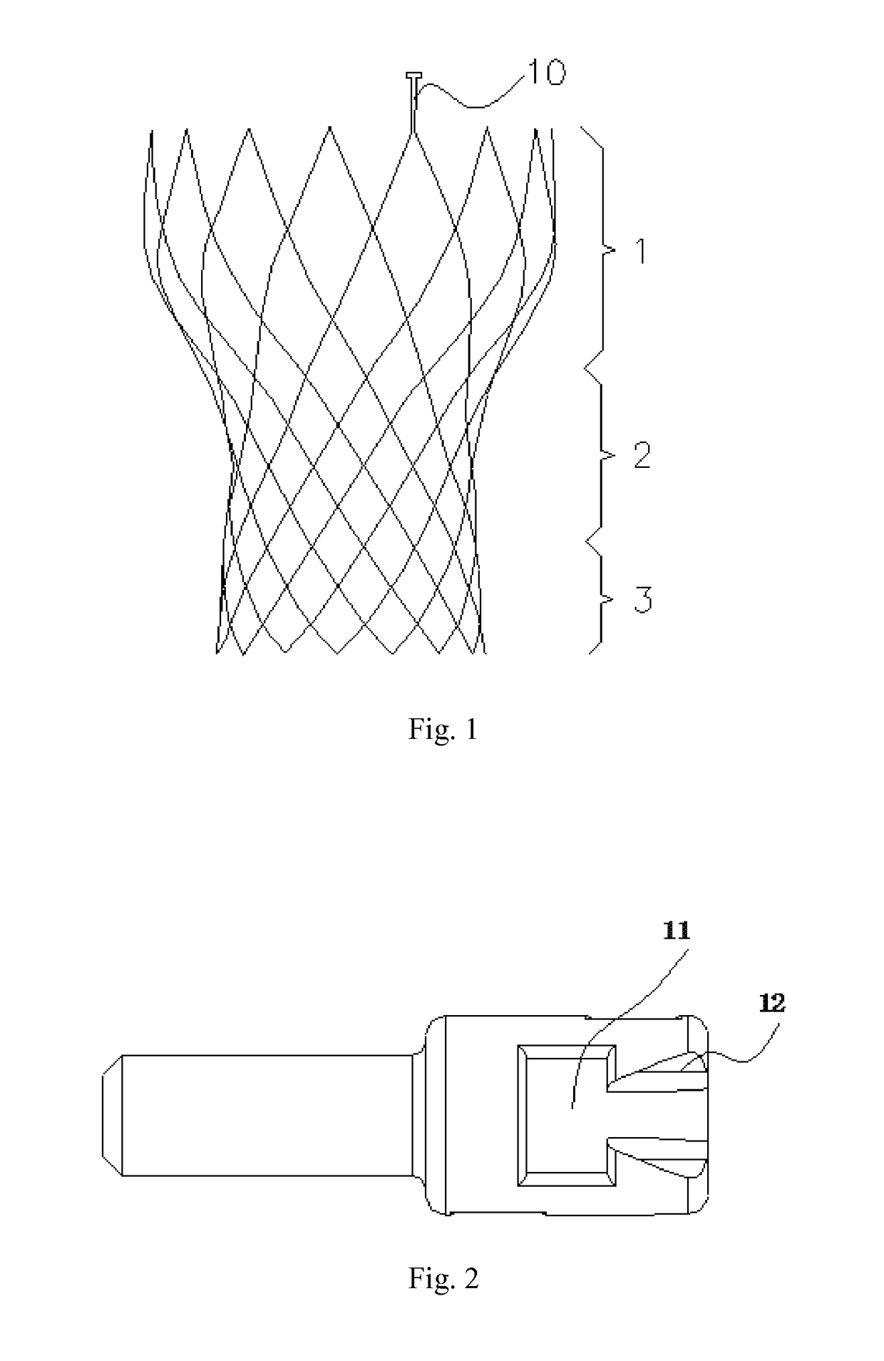
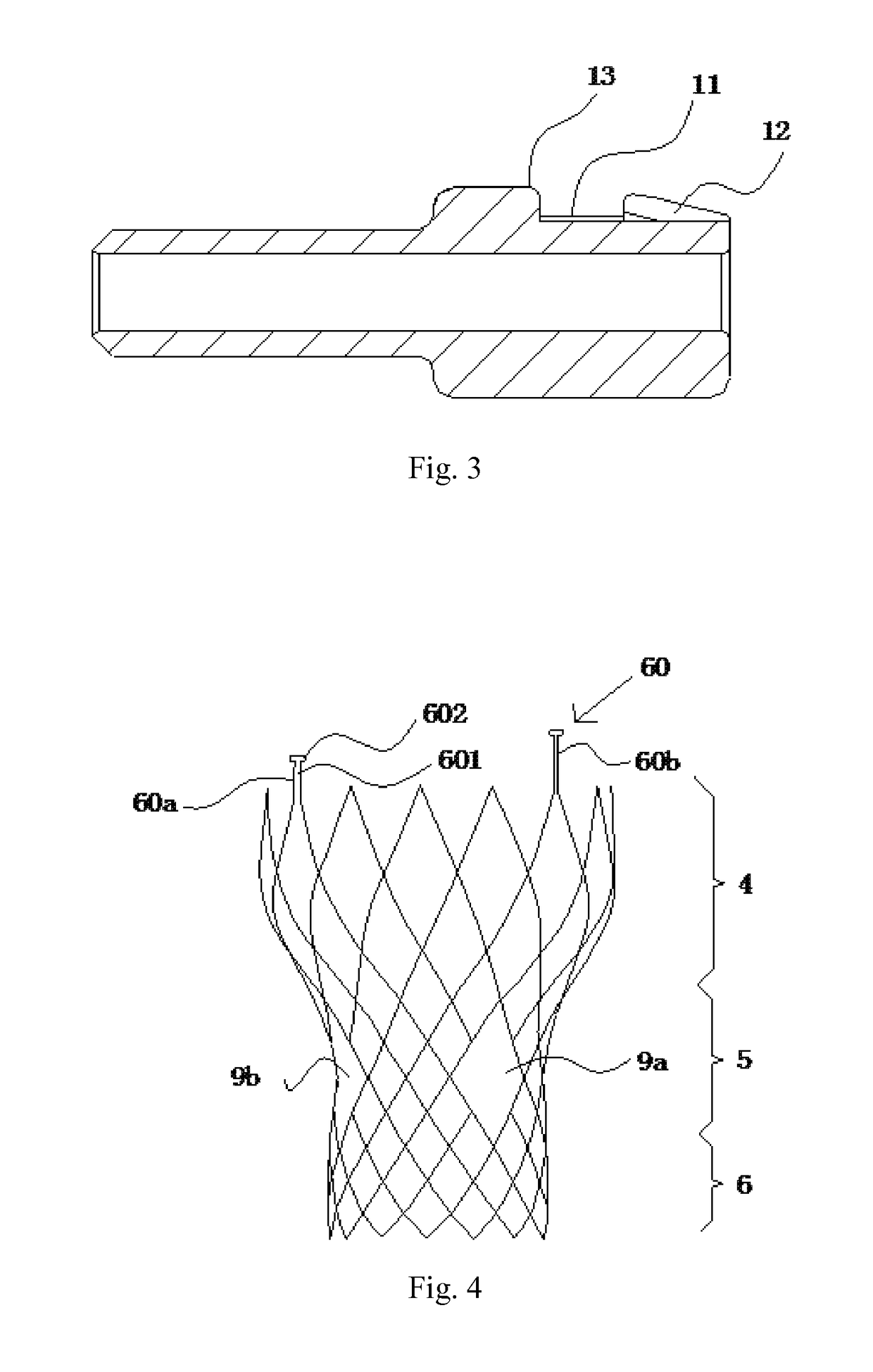
The patent describes a stent which is a cylindrical structure with a top edge that has at least one fixed ear. The fixed ear has a neck portion that connects to the top edge of the stent and a head portion that engages with a stent fixing head. The head portion has a bent structure that increases the overall radial thickness of the stent. The stent is designed to be simple, convenient, and easy to operate on the basis of conventional stents. The technical effect of this design is increased flexibility and better placement of the stent in the body.

Problems solved by technology

When a patient's own heart valves (the mitral valve, the tricuspid valve, the aortic valve, or the pulmonary valve) mutate due to congenital or acquired diseases and hence the valves are unable to open and close normally, health and even life may be adversely affected.
If the artificial valve replacement device is accidentally released, the life safety of the patient will be seriously threatened.
Since there is a clearance with a width of about 0.1-0.2 mm between the stent fixing head and the inner wall of the sheath tube, and the transport system needs to pass the tortuous and complex vasculature system to transport the artificial valve replacement device to the implantation point, when the transport system turns, the sheath tube is bent and deformed, and thus the stent fixed ear is prone to slide out along the clearance, resulting in disengagement of the artificial valve replacement device.
If a thickness of the stent increases, not only does the processing difficulty increase, but also the compliance and expanding performance of the stent are affected.

Method used


Image

  • Stent and securely-installed artificial valve replacement device having same
  • Stent and securely-installed artificial valve replacement device having same
  • Stent and securely-installed artificial valve replacement device having same

Examples


first embodiment

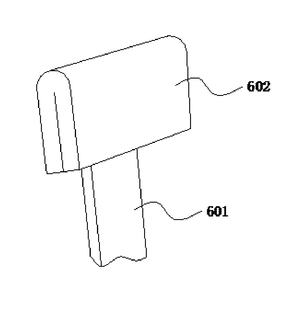
[0058]FIG. 5 illustrates the bent structure of the head portion 602 of the fixed ear 60 of the present application. In this embodiment, the whole head portion 602 of the fixed ear is bent to be arc-shaped, and a concave portion of the arc shape is positioned towards an axis of the stent. In this way, an overall radial thickness H of the head portion 602 (i.e., a difference between a height of a middle portion of the arc shape and a height of either end of the arc shape) is increased. When the fixed ear 60 engages with a positioning groove, as shown in FIG. 7, a depth of a positioning groove 8 of a stent fixing head 7 can be increased appropriately (however, it is also possible that the depth is not increased), so that the head portion 602 of the fixed ear 60 is in tight contact with an inner wall of a sheath tube 14. Of course, when the depth of the positioning groove 8 is increased, the depth can be fit for the thickness of the head portion 602 of the fixed ear 60, as shown in FIG....

second embodiment

[0060]FIG. 8 illustrates the bent structure, wherein the head portion 602 of the fixed ear 60 is substantially wave-shaped, and wave peaks and wave troughs of the wave-shaped head portion 602 are alternately arranged along a circumference of the stent. In particular, two ends of the head portion 602 that abut a bottom of the positioning groove 8 are wave troughs of the head portion 602, so that the fixed ear 60 can be embedded in the positioning groove 8 of the stent fixing head 7 more stably. FIG. 9 and FIG. 10 show mounted states of the head portion 602 of the wave-shaped fixed ear 60 in the transport system when mounting the stent.

third embodiment

[0061]In the bent structure of the head portion 602, the head portion 602 of the fixed ear 60 is partially bent, in particular, two side edges of the head portion 602 are bent towards each other. As shown in FIG. 11, the two side edges of the head portion 602 are bent towards the same side, the bent angle of each side edge equals 180 degrees, and a thickness of the bent fixed ear 60 equals two times of a thickness of the fixed ear 60 before being bent.

[0062]Of course, the two side edges of the head portion 602 can also be bent towards two opposite sides respectively, so that the head portion 602 is substantially S-shaped.


PUM


Abstract

A stent and a securely-installed artificial valve replacement device having the same, the stent being of a cylindrical structure; the top of the stent is provided with a fixed ear (60); the fixed ear (60) has a neck portion (601) connected to the top of the stent, and a head portion (602) engaged with the fixed head of the stent; the head portion (602) has a bending structure for improving the overall radial thickness; and the artificial valve replacement device is comprised of a stent and a prosthetic valve fixed on the stent. The stent with a bending structure overcomes the problem of easily disengaging from the fixed head of the stent, while not affecting the release of the stent.

Description

FIELD OF THE INVENTION[0001]The present application relates to the technical field of medical apparatuses, and more particularly to a stent and a securely-installed artificial valve replacement device having same.BACKGROUND OF THE INVENTION[0002]When a patient's own heart valves (the mitral valve, the tricuspid valve, the aortic valve, or the pulmonary valve) mutate due to congenital or acquired diseases and hence the valves are unable to open and close normally, health and even life may be adversely affected. The mutations of the heart valves include opening incompletely and closing incompletely, both the two situations may result in increase of cardiac load, and whether the heart can normally work under the increasing load is a main basis that determines whether the human body heart valves need to be replaced.[0003]Implantation of artificial heart valves by interventional operations causes small traumas to human bodies and has a low invasion degree, and thus it is applied more and...

Claims


Application Information

Patent Timeline
Patent Type & Authority Patents(United States)
IPC IPC(8): A61F2/82A61F2/962A61F2/90A61F2/91A61F2/966A61F2/24A61F2/95
CPCA61F2/90A61F2/2436A61F2/962A61F2/2418A61F2250/0039A61F2/24A61F2/82A61F2/91A61F2/95A61F2002/9522A61F2002/9665A61F2210/0014A61F2220/0008A61F2220/0033A61F2230/0006A61F2230/0019A61F2230/0021A61F2230/0069A61F2250/0036A61F2250/0037A61F2/9522A61F2230/0052A61F2220/0025A61F2002/91575A61F2002/9505A61F2002/91525A61F2/89A61F2/966A61F2250/0052
Inventor LEI, RONGJUNZHANG, ZHIFEIZHANG, QIMING
Owner VENUS MEDTECH (HANGZHOU) INC
Learn More