
Water heater having a supplemental photovoltaic heating arrangement

a photovoltaic heating and water heater technology, applied in the field of water heaters, can solve the problems of less efficient tank heat loss in idle state, well insulated water heaters experiencing some standby loss, etc., and achieve the effect of less energy consumption, less energy usage, and low set point temperatur

Active Publication Date: 2018-09-11
RHEEM MFG CO
View PDF20 Cites 12 Cited by
  • Summary
  • Abstract
  • Description
  • Claims
  • Application Information

AI Technical Summary

Benefits of technology

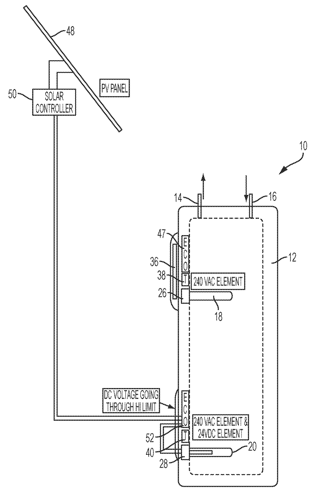
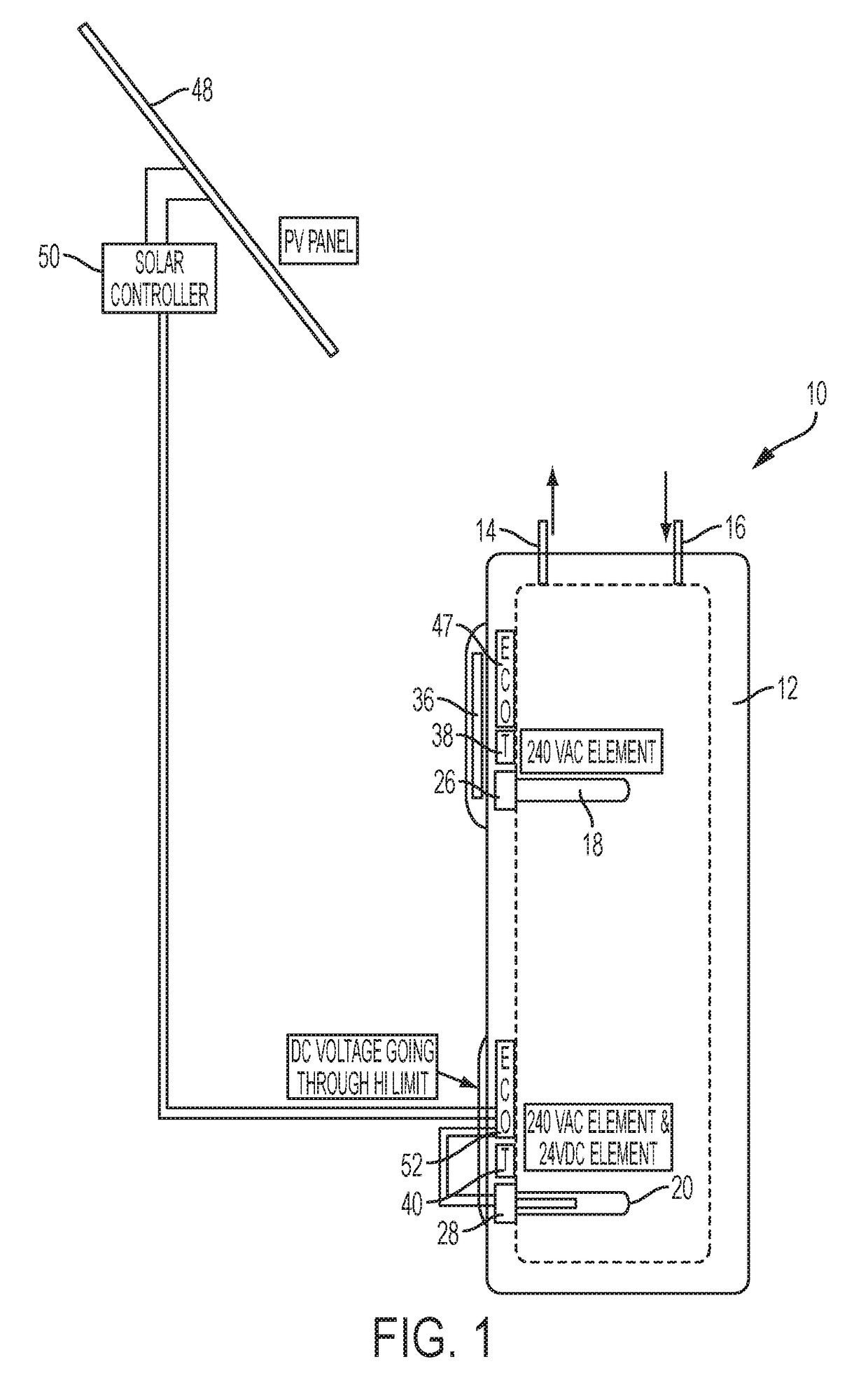
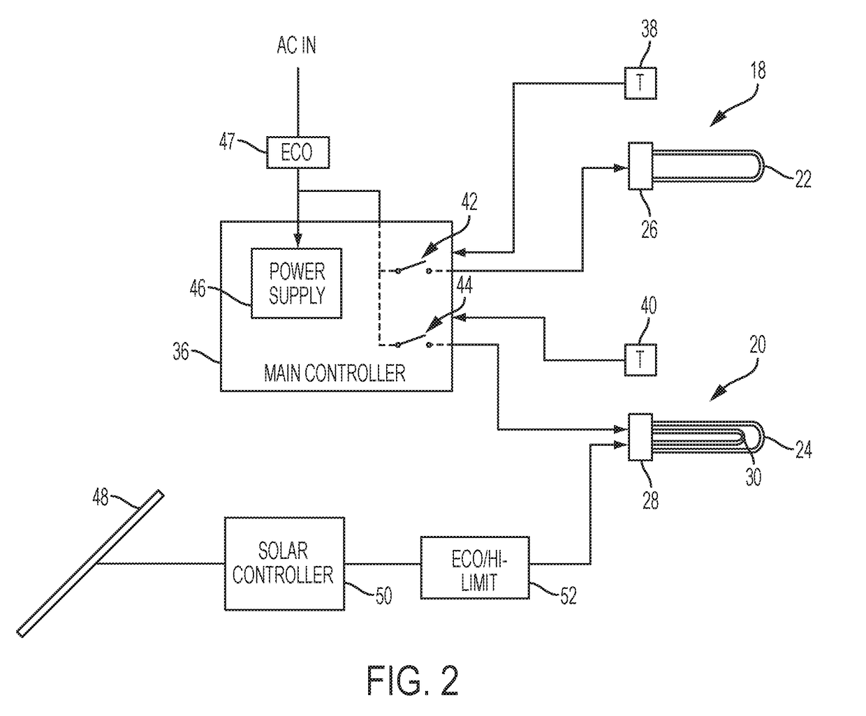
The present invention provides a water heater with a primary heating arrangement and a supplemental heating arrangement to reduce energy usage during standby periods. The primary heating arrangement uses AC power to heat the water, while the supplemental heating arrangement uses photovoltaic panels and a supplemental heating element to apply additional heat energy to the water. Control electronics are used to selectively heat the primary and supplemental heating elements based on the water temperature detected by thermostats. The supplemental heating arrangement can also include a high temperature limit switch to disconnect the photovoltaic energy if a predetermined threshold temperature is reached. The method of controlling the water heater involves providing a solar heating arrangement to supply additional heat energy when the sun is available, and selectively operating the primary heating arrangement to also supply heat energy to the water while the solar heating arrangement is in use. The technical effects of this invention include reducing energy usage, improving efficiency, and controlling the water temperature during standby periods.

Problems solved by technology

Heat loss over a period of time (i.e., standby loss) or usage of the water heater capacity determines the demand for hot water.
Thus, tanks that exhibit greater heat loss in the idle state are less efficient than those that exhibit less standby heat loss because more electric (or gas) energy is required to maintain the desired temperature.
However, even very well insulated water heaters experience some standby loss.

Method used


Image

  • Water heater having a supplemental photovoltaic heating arrangement
  • Water heater having a supplemental photovoltaic heating arrangement
  • Water heater having a supplemental photovoltaic heating arrangement

Examples


Embodiment Construction

[0025]It is to be understood by one of ordinary skill in the art that the present discussion is a description of exemplary embodiments only, and is not intended as limiting the broader aspects of the present invention, which broader aspects are embodied in the exemplary constructions.

[0026]Presently-described embodiments provide a water heater having a supplemental photovoltaic (e.g., solar) heating arrangement which at least partially offsets standby losses that might otherwise occur. The energy produced by one or more relatively small and easily-installable photovoltaic panels preferably contributes energy equal to or greater than typical standby loss. Because modern water heaters are generally well-insulated, this can often be achieved by a solar energy contribution which is less than about 5% of the water heater's total energy consumption. Water heaters constructed in accordance with the present invention may often achieve an Energy Factor (EF) of greater than 1.0.

[0027]Referrin...


PUM


Abstract

A water heater is provided having an insulated tank having a water inlet and a water outlet, and further defining an interior volume to contain a quantity of water. A primary heating arrangement applies heat energy to the water so as to heat the water. In addition, the primary heating arrangement is configured to maintain the water during standby periods between upper and lower set point temperatures. A supplemental heating arrangement is operative to supply additional heat energy to the water in order to lessen energy usage by the primary heating arrangement during the standby periods. In accordance with a preferred embodiment, the supplemental heating arrangement includes at least one photovoltaic panel and a supplemental heating element. Control electronics are operatively interposed between the at least one photovoltaic panel and the supplemental heating element.

Description

CLAIM OF PRIORITY[0001]This application claims priority to U.S. Provisional Application No. 62 / 099,529, filed Jan. 4, 2015, the entire disclosure of which is incorporated by reference herein.BACKGROUND OF THE INVENTION[0002]The present invention relates generally to water heaters. More particularly, the present invention relates to a water heater in which a primary heating arrangement (e.g., electric or gas) is supplemented by a photovoltaic heating arrangement.[0003]Typical water heaters have a tank in which a quantity of heated water is maintained for use as needed. Generally speaking, such water heaters fall into one of two categories, i.e., electric or gas, depending on the type of heat source used to bring the water in the tank up to the desired temperature. Electric water heaters, for example, are often configured having two electric heating elements near the top and the bottom of the tank, respectively. Typically, the heating elements are energized by AC voltage (such as 240 ...

Claims


Application Information

Patent Timeline
Patent Type & Authority Patents(United States)
IPC IPC(8): F24H1/18F24H1/20F24D17/00F24D3/00F24D19/10F24H9/20F24D18/00
CPCF24D19/1075F24D3/005F24D17/0021F24D17/0031F24D19/1069F24D19/1081F24H9/2021F24H1/202Y02B10/70F24D2200/02F24D2200/08F24H2240/09Y02B10/20F24D19/1057F24D18/00F24D2101/40F24H15/156F24H15/37F24H15/174F24H15/25F24H15/128F24H15/414
Inventor CHAUDHRY, RAHEEL A.HINTON, ARTHUR Y.BOROS, JOZEF
Owner RHEEM MFG CO
Learn More