
Prosthetic attachment

a technology for prosthetic arms and hands, applied in the field of prosthetic arms, can solve the problems of many prosthetic arms not having a permanent hand, time-consuming and difficult for individuals with multiple limbs

Inactive Publication Date: 2018-08-14
ARMBRUSTER MICHAEL
View PDF4 Cites 3 Cited by
  • Summary
  • Abstract
  • Description
  • Claims
  • Application Information

AI Technical Summary

Problems solved by technology

Many prosthetic arms will not contain a permanent hand.
For example, the user may be in a social setting and might therefore want the attachment to resemble a traditional hand, even though the hand may have limited functionality.
This can be time consuming and very challenging to individuals with multiple limb problems, children or the elderly.

Method used


Image

  • Prosthetic attachment
  • Prosthetic attachment
  • Prosthetic attachment

Examples


Embodiment Construction

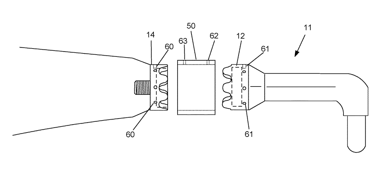
[0020]In the present invention, a base is screwed into the wrist of the user's [already existing] prosthetic arm. This base contains an embedded magnet. A prosthetic attachment includes a prosthetic attachment piece that also has an embedded magnet. The user can simply place the base near the attachment piece, the magnets will then attract to each other, and the prosthetic attachment will click into place. Removing the attachment is equally as easy given it can be pulled away without the need of a fully developed hand. The base has curved teeth, (hereinafter referred to as “valleys and peaks”), along the perimeter. This prevents unwanted clockwise and counter-clockwise movement, while still allowing the user to easily adjust the attachment to the appropriate angle. Finally, in a preferred embodiment the invention contains a basic locking mechanism for applications where the magnetic pull alone might not be strong enough to keep the attachment in place, such as lifting a heavy object...


PUM


Abstract

A prosthetic attachment for a prosthetic limb. A base is attached to the prosthetic limb. The base has a magnet that is surrounded by base valleys and base peaks. An attachment piece is attached to the prosthetic attachment. The attachment piece also has a magnet that is surrounded by attachment piece valleys and attachment piece peaks. The magnetic force between the base magnet and the attachment piece magnet attracts the prosthetic attachment to the prosthetic limb so that the base peaks and valleys mates with the attachment piece peaks and valleys for a secure removable attachment. In a preferred embodiment a locking device is used to further secure the prosthetic attachment to the prosthetic limb. In a preferred embodiment the prosthetic attachment is a prosthetic hand and the prosthetic limb is a prosthetic arm.

Description

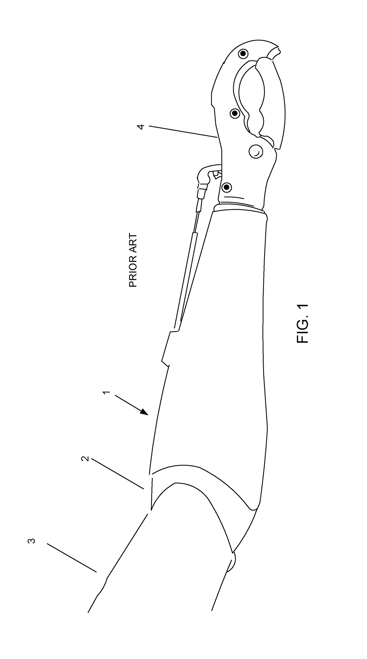
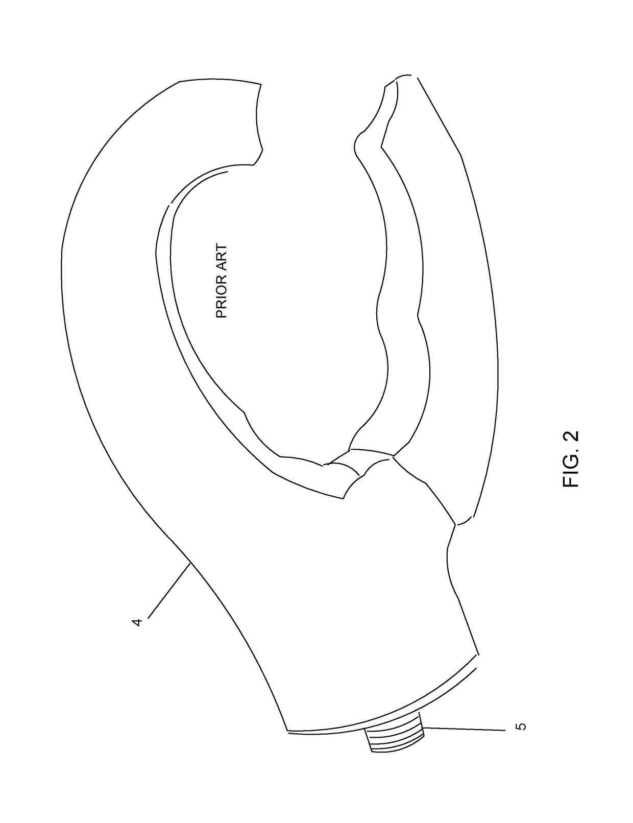
[0001]The present invention relates to prosthetic limbs, and in particular, to prosthetic attachments to prosthetic limbs.BACKGROUND OF THE INVENTION[0002]Prosthetic arms are well known. A prosthetic arm is an artificially made substitute for an arm, or portion of an arm, that was perhaps lost through a congenital defect, accident, illness, or wartime injury.[0003]Many prosthetic arms will not contain a permanent hand. Rather, the prosthetic arm will end at the wrist, wherein the user can then screw in the hand (hereinafter “prosthetic attachment”). FIG. 1 shows prosthetic attachment 4 removably attached to prosthetic arm 1. It is desirable to have attachments that are removable so that the user may change the style depending upon the current need. For example, the user may be in a social setting and might therefore want the attachment to resemble a traditional hand, even though the hand may have limited functionality. On another occasion the user may need to do a lot of heavy lifti...

Claims


Application Information

Patent Timeline
Patent Type & Authority Patents(United States)
IPC IPC(8): A61F2/54A61F2/58A61F2/76A61F2/56B25J15/04A61B50/20A61F2/50B25J15/06
CPCA61F2/588A61F2/76A44D2203/00A61B2050/21B25J15/0608A61F2002/5083A61F2210/009A61F2220/0041B25J15/0441A61F2002/5018
Inventor ARMBRUSTER, MICHAEL
Owner ARMBRUSTER MICHAEL
Learn More