Resin molded body and method of molding the same
一种树脂成型体、成型体的技术,应用在薄料处理、运输和包装等方向,能够解决安装支座裂开、变形等问题,达到提高刚性、防止变形和损坏、刚性提高的效果
- Summary
- Abstract
- Description
- Claims
- Application Information
AI Technical Summary
Problems solved by technology
Method used
Image
Examples
no. 1 example
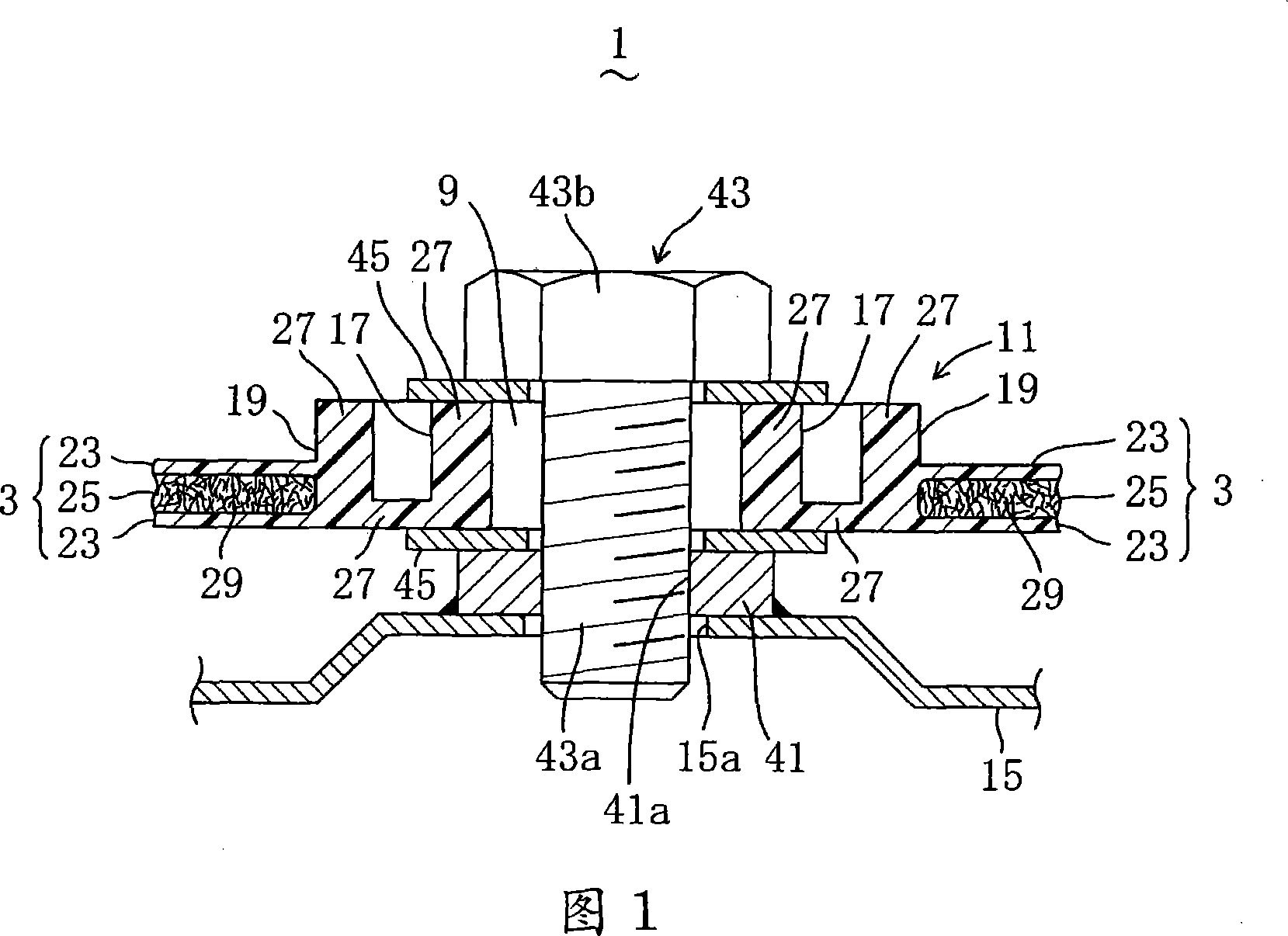
[0040] 3 is a perspective view of a resin door inner panel (door module) 1 viewed from the inside of the vehicle interior. The resin door inner panel 1 constitutes an automobile as a resin molded body according to the first embodiment of the present invention. Part of the side door. The door inner panel 1 includes a door inner panel main body (hereinafter, the door inner panel main body is referred to as a panel main body) 3 as a molded body. A protruding cylindrical mounting bracket 5 is integrally provided with the panel main body 3 at each position. The mounting bracket 5 is used for installing a window glass lifting track (not shown). On the surface of the panel body 3 in FIG. 3 corresponding to the lower left corner, on the vehicle outer side, a protruding, circular, flowerpot-shaped speaker housing portion 7 is provided integrally with the panel body 3. . A plurality of circular through-holes 9 are formed around the panel body 3 at a portion near the inner side of the...
no. 2 example
[0049] FIG. 6 is a view corresponding to FIG. 1 of the door inner panel 1 as a resin molded body according to the second embodiment of the present embodiment; FIGS. 7 and 8 are molding processes corresponding to FIGS. 4 and 5 . picture.
[0050] In this second embodiment, protruding mounting seats 11 are provided integrally with the panel body 3 on both surfaces of the panel body 3 so that all the mounting seat parts 17, 19, and 21 face each other and overlap each other when viewed from above. . The mounting supports 11 jointly have a through-hole 9 .
[0051] In order to provide protrusions and opposite mounting supports 11 on both surfaces of the panel main body 3, recesses 31b, 31c are also formed in the first die 31 of the molding die 37 used in this second embodiment, and the pressing blocks 35 Same. The recesses 31b, 31c are opposed to the recesses 35a, 35b.
[0052] Since the other parts are constructed in the same manner as in the first embodiment, the same structu...
no. 3 example
[0056] FIG. 9 is a view corresponding to FIG. 1 of the door inner panel 1 as a resin molded body according to the present embodiment, that is, the third embodiment.
[0057] In the third embodiment, a solid layer 27 excluding the expansion layer 25 is formed near the outer surface of the mounting base 11 of the panel body 3 , and the solid layer 27 continuously surrounds the mounting base 11 and has a predetermined width. Not shown in the drawings, corresponding to the solid layer 27 , in the pressing block 35 of the molding die 37 used in the third embodiment, an annular convex portion is formed outside the concave portion 35b.
[0058] Since the other parts are constructed in the same manner as in the first embodiment, the same structural parts are denoted by the same symbols, and detailed descriptions of these parts are omitted. Likewise, the description of the molding method is also omitted.
[0059] With this configuration, in this third embodiment, the same operation as...
PUM
 Abstract
Description
Claims
Application Information
 - R&D
- Intellectual Property
- Life Sciences
- Materials
- Tech Scout
- Unparalleled Data Quality
- Higher Quality Content
- 60% Fewer Hallucinations
Browse by: Latest US Patents, China's latest patents, Technical Efficacy Thesaurus, Application Domain, Technology Topic, Popular Technical Reports.
© 2025 PatSnap. All rights reserved.Legal|Privacy policy|Modern Slavery Act Transparency Statement|Sitemap|About US| Contact US: help@patsnap.com


