Electric-cable core temperature on-line monitoring system

A monitoring system and cable technology, applied in thermometers, thermometers using electric/magnetic elements that are directly sensitive to heat, thermometers that use physical/chemical changes, etc., can solve problems such as high cost and affecting power grid efficiency

Inactive Publication Date: 2007-06-20
李志坚
View PDF0 Cites 15 Cited by
  • Summary
  • Abstract
  • Description
  • Claims
  • Application Information

AI Technical Summary

Problems solved by technology

There are two solutions: the first is to replace large cross-section cables, or to lay new cables in parallel, which requires a lot of expenses; in additi...

Method used


Image

  • Electric-cable core temperature on-line monitoring system
  • Electric-cable core temperature on-line monitoring system
  • Electric-cable core temperature on-line monitoring system

Examples


Embodiment Construction

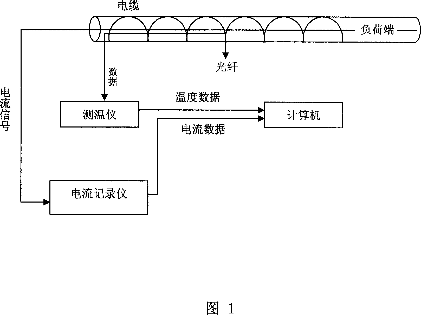
[0027] Referring to Figure 1, the analog quantities of temperature and load current are converted into digital signals in real time through the thermometer and current recorder, and input into the computer as raw data, and the cable core temperature is calculated in real time by the calculation program, and displayed in the most intuitive way . The calculation program can be switched to different screens to display the temperature change of each point along the cable, and also can display the temperature change process of a certain point of the cable with time. The temperature measuring element in the online monitoring system of cable core temperature can use optical fiber or thermocouple, that is, any one of optical fiber or thermocouple can be used as the temperature measuring element.

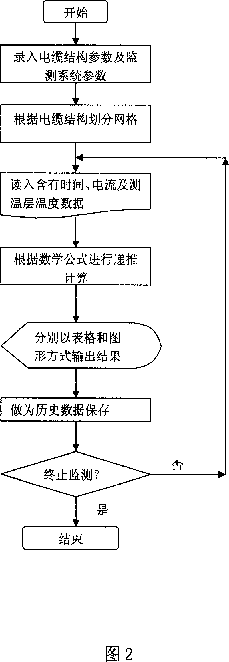
[0028] Referring to Figure 2, in the calculation program flow, first input the cable structure parameters (such as the number of layers of the cable and the thickness of each layer, volume s...


PUM


Abstract

An on-line monitoring system of power cable core temperature comprises cable, temperature measurement element set on surface of power cable, current recorder and temperature measure connected separately to cable and temperature measurement element. It is featured as converting collected current and temperature analog signals to be digital signals by current recorder and temperature measurer then sending digital signals to computer with calculation program.

Description

technical field [0001] The invention relates to a cable temperature monitoring system, in particular to an on-line monitoring system which monitors the load current of the cable and the temperature of the cable surface (or a certain layer inside) in real time, and uses a calculation program to calculate the core temperature of the power cable. technical background [0002] At present, the vast majority of urban areas use cable power supply. Due to the rapid growth of power consumption, concentrated loads, and large peak-to-valley differences, the cable power supply network is under great power supply pressure during peak load periods. Power cuts have to be taken during peak hours. There are two solutions: the first is to replace large-section cables or lay new cables in parallel, which requires a lot of expenses; in addition, if the load capacity of the cables is designed according to the peak load, it will inevitably increase investment and affect the efficiency of the powe...

Claims


Application Information

Patent Timeline
IPC IPC(8): G01K11/32G01K7/02
Inventor 郝文霞蒋亦兵杨华张东斐付兴王芹刘建忠葛荣钢
Owner 李志坚
Why Eureka
Try Eureka