
Double-outputting torque speed reducing electric machine

A deceleration motor and dual output technology, applied in the direction of electrical components, electromechanical devices, mechanical equipment, etc., can solve the problems of unfavorable automatic control, waste of power configuration, complex structure, etc., and achieve the advantages of automatic control, simple structure, and simple switching Effect

Inactive Publication Date: 2007-06-06
卢能晓
View PDF0 Cites 28 Cited by
  • Summary
  • Abstract
  • Description
  • Claims
  • Application Information

AI Technical Summary

Problems solved by technology

The speed ratio reduction motor is adjusted by adjusting the transmission ratio of the gear, and the adjustment range is wide. However, on some equipment that only needs to be adjusted in two gears, fast and slow, it is not applicable due to its complex structure and high cost, and its adjustment requires mechanical action. It is not conducive to automatic control; while using a fixed speed ratio reduction motor, when speed regulation is required, the motor speed can be adjusted by adjusting the motor voltage and other parameters to achieve the speed adjustment of the output shaft, but because the motor power decreases, the output torque decreases accordingly. Small
For example, when an electric vehicle goes uphill, it needs to reduce the speed and increase the torque. The existing technology uses a high-power motor to meet the power needs of heavy loads such as loads and uphill loads. High power is required, resulting in a waste of power configuration and increasing the cost of the vehicle

Method used


Image

  • Double-outputting torque speed reducing electric machine

Examples


Embodiment Construction

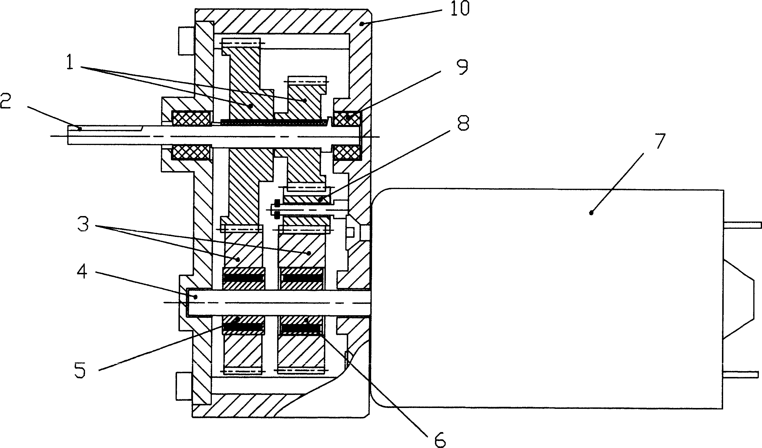
[0009] As shown in the figure, the geared motor with double output torque of the embodiment includes a motor 7 and a gear reduction mechanism, and two one-way bearings are arranged on the motor shaft 4, which are forward rotation one-way bearing 5 and reverse rotation one-way bearing 6 respectively. , there are two sets of gear sets in the gear reduction mechanism. Among the two sets of gear sets, the number of gears in one set is one more than the other set. Therefore, for the comparison of the steering of the output shaft 2 and the motor shaft 4, one set is It is the same as the steering transmission reduction gear set, and the other set is the reverse steering transmission reduction gear set. The two input teeth 3 of the two reduction gear sets are respectively sleeved on the two one-way bearings, and the two output teeth 1 are fixedly sleeved together. on output shaft 2.

[0010] When the rotating shaft 4 of the motor 7 rotates forward, the reverse one-way bearing 6 sleeve...


PUM


Abstract

A speed reduction motor with double output-torque is prepared as setting two one-way bearings on motor rotary shaft as one being positive rotation bearing and another being negative rotation bearing, setting two sets of gear groups in gear speed reduction mechanism as one being same-direction speed reduction gear group and another being reverse-direction speed reduction gear group, jacketing two input teeth separately on two one-way bearings and firm-jacketing two output teeth commonly on output shaft.

Description

technical field [0001] The invention relates to a reduction motor, especially the improvement of its reduction mechanism. Background technique [0002] Geared motors are widely used in mechanical equipment. The existing geared motors are composed of a motor and a gear reduction mechanism. According to the structure of the reduction mechanism, they are divided into fixed speed ratio geared motors and variable speed ratio geared motors. The speed ratio reduction motor is adjusted by adjusting the transmission ratio of the gear, and the adjustment range is wide. However, on some equipment that only needs to be adjusted in two gears, fast and slow, it is not applicable due to its complex structure and high cost, and its adjustment requires mechanical action. It is not conducive to automatic control; while using a fixed speed ratio reduction motor, when speed regulation is required, the motor speed can be adjusted by adjusting the motor voltage and other parameters to achieve the...

Claims


Application Information

Patent Timeline
Patent Type & Authority Applications(China)
IPC IPC(8): H02K7/116F16H1/20
Inventor 金拓
Owner 卢能晓
Learn More