
Magnetic head unit

A magnetic head device and magnetic function technology, applied in the configuration/installation of the recording head, supporting the head, magnetic recording, etc., can solve the problems of reducing the floating distance of the slider, reducing the magnetic function part, and reducing the floating amount of the magnetic head, so as to avoid damage Effect

Inactive Publication Date: 2007-06-06
TDK CORPARATION
View PDF1 Cites 4 Cited by
  • Summary
  • Abstract
  • Description
  • Claims
  • Application Information

AI Technical Summary

Problems solved by technology

Although it can be considered that the negative pressure generating parts arranged in front and back can reduce the floating amount of the entire magnetic head and reduce the distance between the magnetic function part and the surface of the recording medium, if the air density of the use environment is reduced, it is easy to generate front dynamic pressure. Both the part and the rear dynamic pressure generating part are close to the recording medium, and as a result, the floating distance of the slider is reduced

Method used


Image

  • Magnetic head unit
  • Magnetic head unit
  • Magnetic head unit

Examples


Embodiment

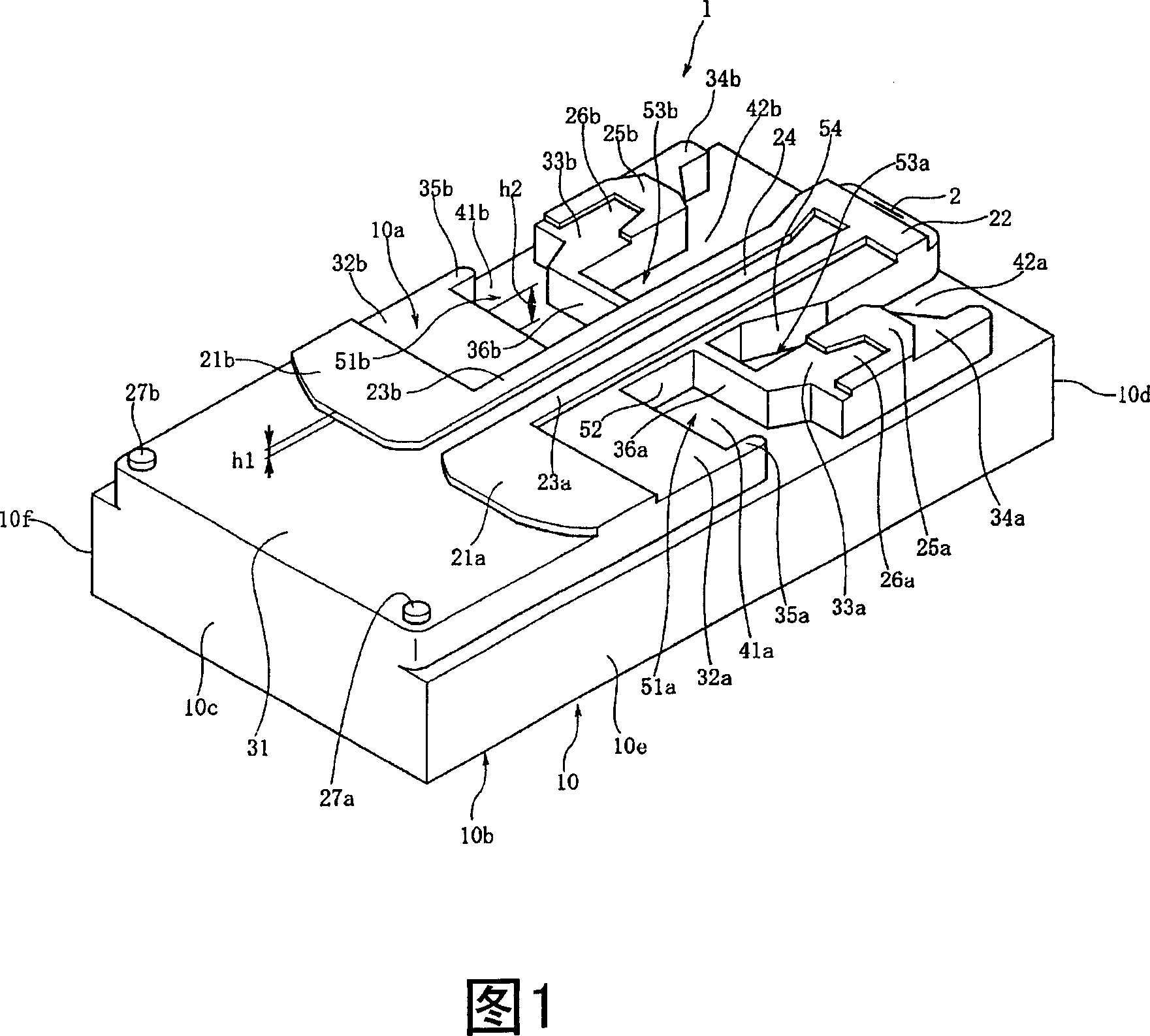
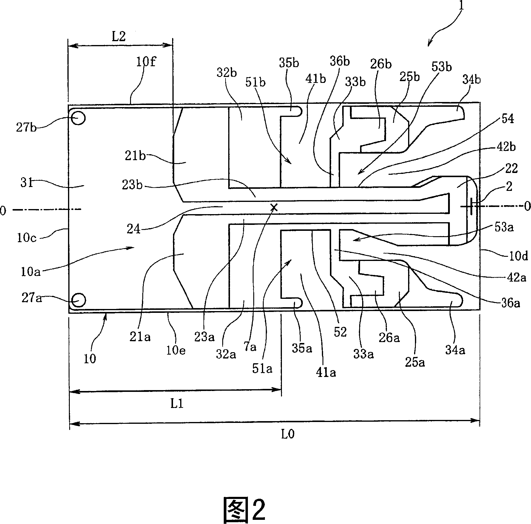
[0078] A slider having the same structure as the magnetic head device 1 of the embodiment and the magnetic head devices 1A and 1B of the modified examples was simulated by computer analysis. In this simulation, the slider 10 of the magnetic head device 1 has a long side of 124 mm, a short side of 0.70 mm, a depth h1 of 0.15 μm, and a depth h2 of 3 μm. The pressing force (load pressure) acting on the contact point 7a toward the recording medium D was 19.6 mN, and the rotational speed of the recording medium D was 3600 rpm.

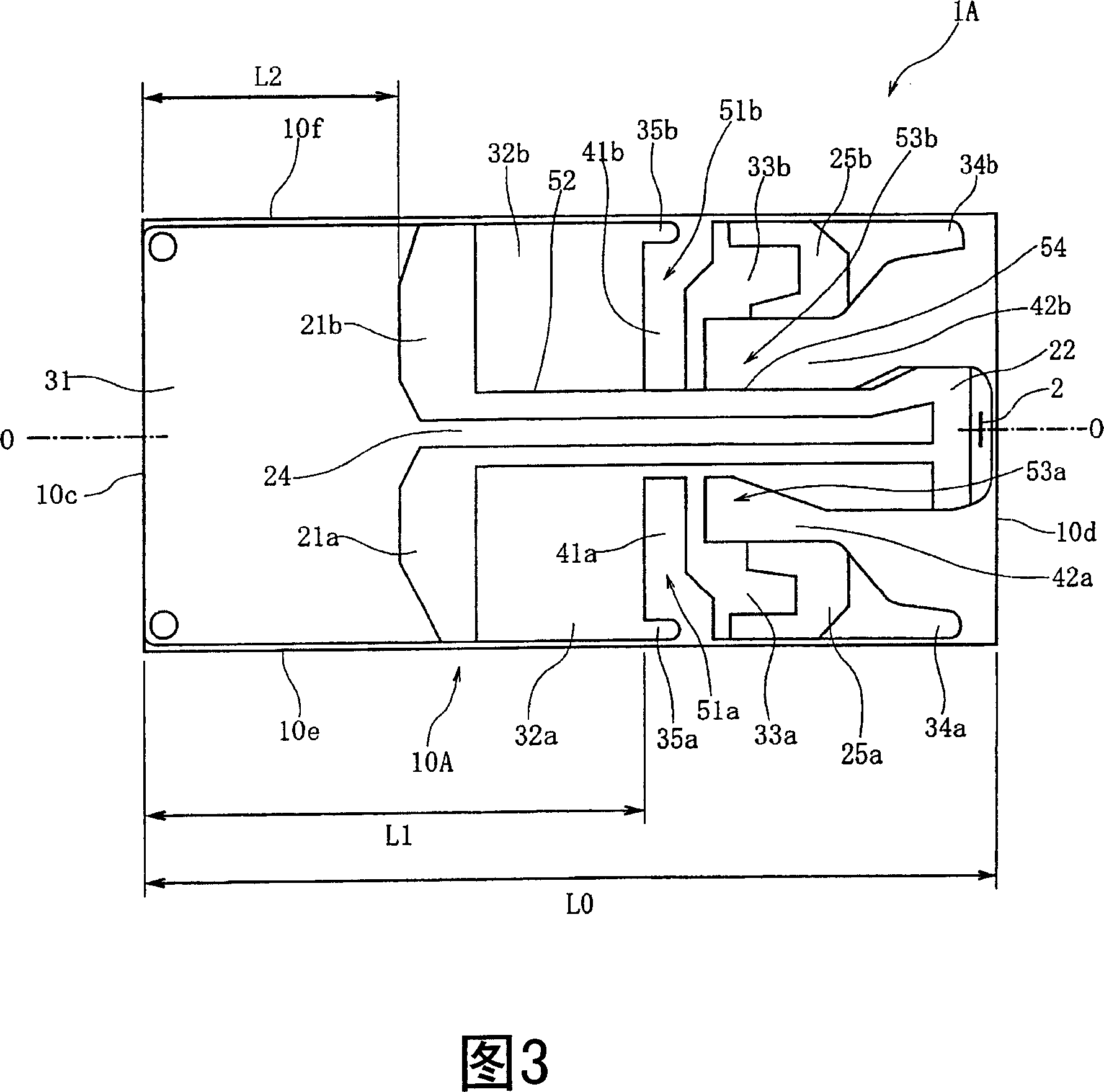
[0079] Simulations were performed for Comparative Examples and Examples in which the ratio L1 / L0 of the distance L1 from the guide-side end surface 10c to the tips of the first negative pressure generating portions 51a, 51b and the total length L0 of the slider 10 was changed. As described with reference to the relationship between the embodiment shown in FIGS. 1 and 2 and the modified examples shown in FIGS. 3 and 4, the first front positive pressure surfa...


PUM


Abstract

The present invention provides a magnetic head unit. In the magnetic head unit that is of floating posture on the effection of the air stream formed on its surface when the recording medium moves, the floating posture of the slider is stable, and the floating amount of the magnetic function part is stable even when air density of an environment varies. The first and second front positive pressure surfaces, a rear positive pressure surface, first and second rear side positive pressure surfaces, a first negative pressure generating part and a second negative pressure generating part. The first negative pressure generating part is disposed near the middle point of the slider or in the rear of the slider, the second negative pressure generating part disposed in the rear of the first negative pressure generating part. The change of the floating posture and the fll of the floating distance can be prevented when the air density is reduced, by balancing the floating force acting on every positive pressure surfaces and the absorption force acting on the first negative pressure generating part.

Description

technical field [0001] The present invention relates to a magnetic head device provided with a magnetic functional portion on a slider facing a magnetic recording medium such as a hard disk, and more particularly to a magnetic head device capable of controlling fluctuations in the floating distance from the recording medium when the air density of the use environment changes. Background technique [0002] As a magnetic head device for recording a magnetic signal on a recording medium such as a hard disk or reading a magnetic signal recorded on a magnetic recording medium, a slider facing the magnetic recording medium is used. The device of the magnetic function department. The magnetic functional part includes a reproducing functional part utilizing the MR effect or a GMR effect, and a recording functional part in which a yoke and a coil of a magnetic material are formed with a thin film. [0003] The slider of the magnetic head device is pushed against the surface of the m...

Claims


Application Information

Patent Timeline
Patent Type & Authority Applications(China)
IPC IPC(8): G11B5/60G11B21/21
CPCG11B5/6005
Inventor 近藤康之
Owner TDK CORPARATION
Learn More