
Method for estimating velocity

A speed and monitoring window technology, applied in the field of speed evaluation, can solve problems such as being unsuitable for speed measurement

Inactive Publication Date: 2007-06-06
ROBERT BOSCH GMBH
View PDF0 Cites 0 Cited by
  • Summary
  • Abstract
  • Description
  • Claims
  • Application Information

AI Technical Summary

Problems solved by technology

But the disadvantage of the SRRs is that they are not suitable for speed measurement

Method used


Image

  • Method for estimating velocity
  • Method for estimating velocity
  • Method for estimating velocity

Examples


Embodiment Construction

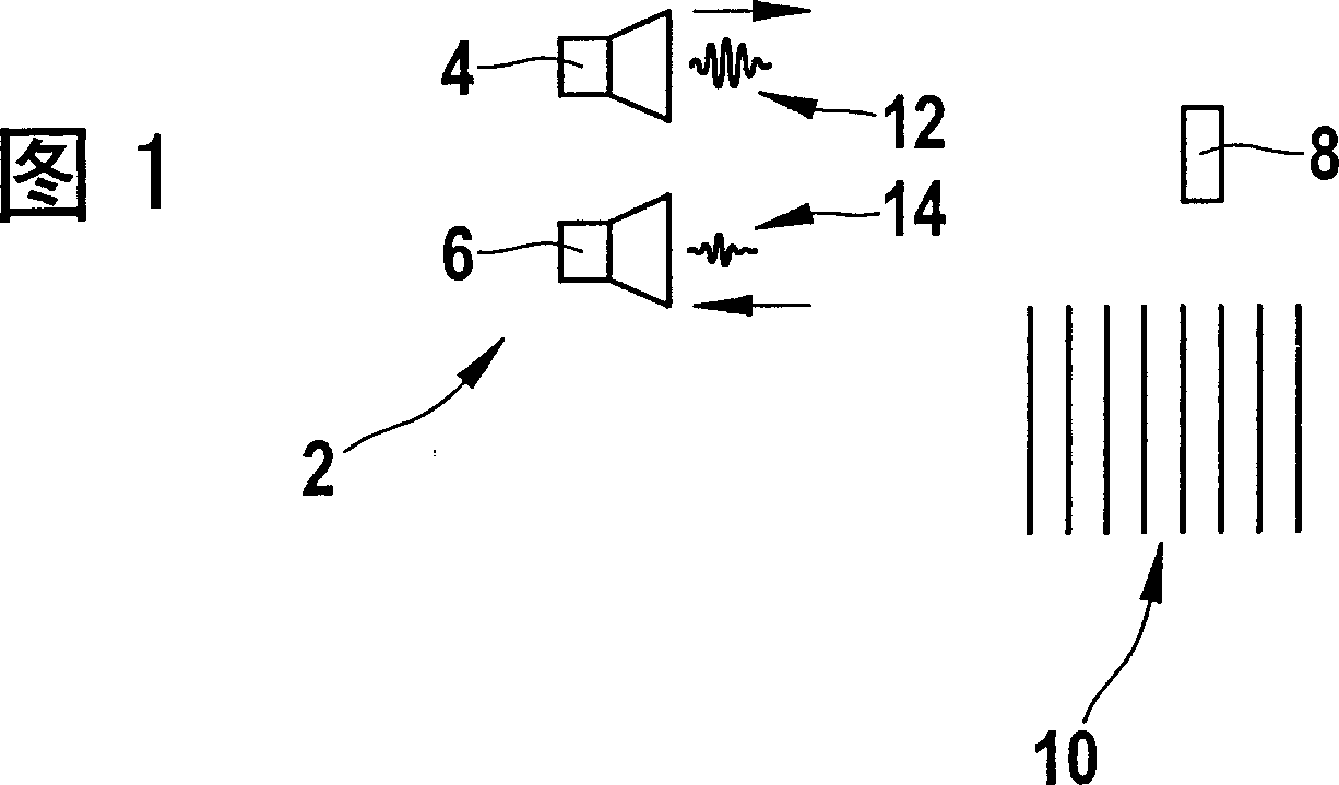
[0031] The device 2 shown schematically in FIG. 1 has a transmitter 4 and a receiver 6 . In order to determine the velocity of a reflector 8 , a distance segment to be detected is divided into a plurality of equidistant partial distance segments separated from one another here by lines, wherein a monitoring window 10 is assigned to each partial distance segment. In the implementation of the method, the sub-distance sections are scanned successively for the monitoring windows 10, where the transmitter 4 sends a transmission signal 12 for each monitoring window 10 to be scanned, which is reflected by the reflector 8 as an echo , and is received by receiver 6 as received signal 14 .

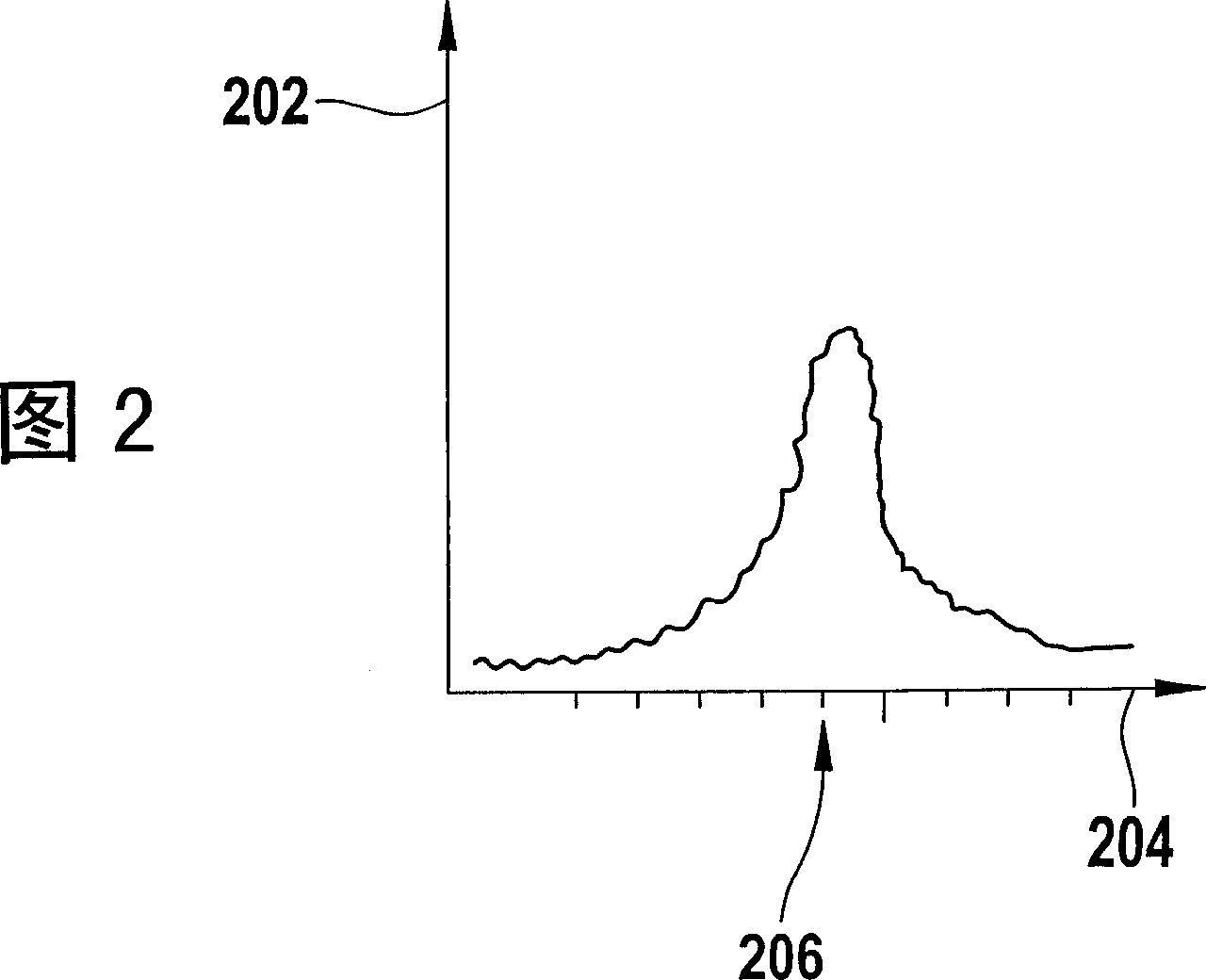
[0032] FIG. 2 shows a graph of the received signal 14 . Here, its magnitude is represented by the ordinate 202 and the distance d by the abscissa 204 . In the implementation of this method, only for the distance d from the device 2 0 The monitor window 10 (point 206 on the abscissa 204) records a...


PUM


Abstract

The present invention relates to a method for estimating the velocity that a reflector moves related to a device. In this method, n surveillance windows are scaned, wherein in each scanning sequence, k surveillance windows are scaned one by one from the i surveillance window, and in the next scanning sequence after every of the said scanning sequence is completed, k surveillance windows are scaned one by one from the i+1 surveillance window, wherein k G01S 13 / 58 3 8 2 2006 / 12 / 4 1975460 2007 / 6 / 6 000000000 Bosch GmbH Robert Federal Schneider Marcus zengli 72002 NTD Patent & Trademark Agency Ltd. Units 1805-6, 18th Floor, Greenfield Tower, Concordia Plaza, No.1 Science Museum Road, Tsimshatsui, east, Kowloon, Hong Kong 100045 Federal 2005 / 12 / 2 102005057570.6

Description

Contents of the invention [0001] The present invention relates to a method for evaluating speed, a device for evaluating speed, a computer program and a computer program product. Background technique [0002] A pulse radar sensor (short pulse radar sensor, SRR) works according to the principle of the pulse-echo method. Here, in one variant, a radar pulse of, for example, 24 gigahertz (GHz) and a pulse width of approximately 30 cm is transmitted from an antenna in the direction of a reflector and a reflected radar pulse is detected by the receiver The time taken to receive. If several reflectors are located in the vicinity of the sensor, several echoes of the radar pulse may be picked up. The distance to these reflectors can be determined from the propagation time of the radar pulse. [0003] In order for a receiver to receive a signal with sufficient energy, a relatively high transmit power is required. The smaller the energy, the harder it is to distinguish the echo pul...

Claims


Application Information

Patent Timeline
IPC IPC(8): G01S13/58
CPCG01S7/2923G01S13/581
Inventor 马库斯·施奈德
Owner ROBERT BOSCH GMBH
Learn More