
Aluminium belt cutting machine

A slitting machine, aluminum strip technology, applied in metal processing, coiling strips, sending objects, etc., can solve the problems of reducing production efficiency, uneven aluminum strip, wrinkling, etc., to achieve stable and reliable work, work efficiency High and easy-to-operate effect

Inactive Publication Date: 2007-06-06
ZHANGJIAGANG LIANYI ELECTRONICS
View PDF0 Cites 8 Cited by
  • Summary
  • Abstract
  • Description
  • Claims
  • Application Information

AI Technical Summary

Problems solved by technology

The disadvantages of the above slitting machine are: the slit aluminum strips are not straight, wrinkled, and have serious burrs on the section; since the slit aluminum strips are all wound on a rewinding shaft, it is very easy to cause adjacent aluminum strips Overlapping and winding each other increases the tediousness of work and reduces production efficiency

Method used


Image

  • Aluminium belt cutting machine
  • Aluminium belt cutting machine
  • Aluminium belt cutting machine

Examples


Embodiment Construction

[0015] The present invention will be further described below in conjunction with the above-mentioned drawings and specific embodiments.

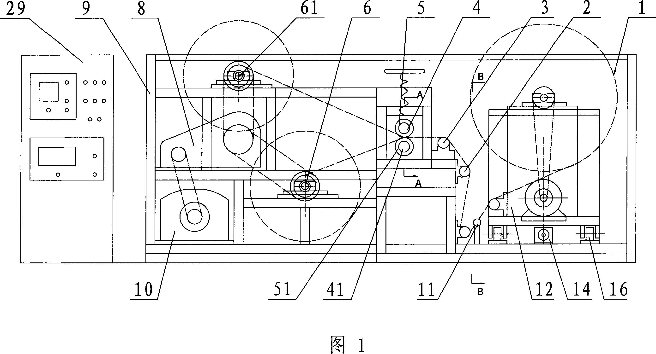
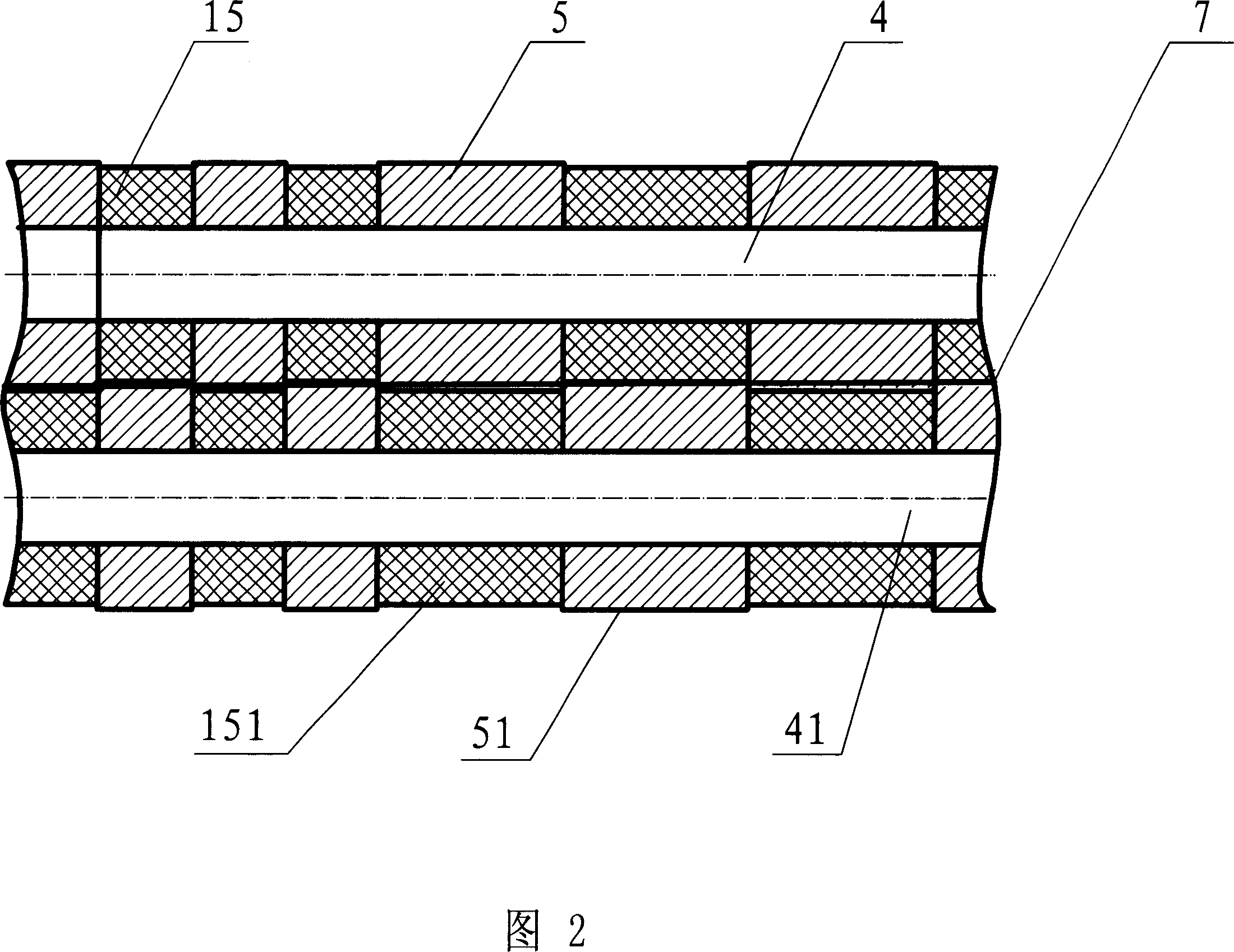
[0016] As shown in Fig. 1 and Fig. 2, the aluminum strip slitting machine according to the present invention includes: a frame 9, and a power transmission device is arranged in the frame 9—mainly including a main motor 10 and a reduction box 8 in this embodiment , the reduction box 8 drives the relevant parts to run again, and two receiving shafts 6 and 61, two cutting blade shafts 4 and 41, some guide shafts 3 and the discharge rack 12, and the controller are also arranged in the frame 9 29. The distance between the two rewinding shafts 6 and 61 can be set according to the size of the frame 9 and the size of the material roll after rewinding, and the number of guide shafts 3 can also be set according to the size of the frame 9 Size and actual working conditions are set; On the cutting blade shafts 4 and 41, disc-shaped cutting blades 5 and ...


PUM


Abstract

The present invention discloses one kind of aluminum belt cutting machine with convenient operation, straight cutting, no bur and stable and reliable operation. The aluminum belt cutting machine includes one chassis, one driving mechanism, two collecting shafts, two cutting blade shafts with cutting blades, several guide shafts and one unwinding frame. Two adjacent disc cutting blades separately on two cutting blade shafts constitute one cutting edge. There is also one deviation corrector set between the unwinding frame and the chassis. The aluminum belt cutting machine is used in cutting aluminum belt as well as other metal or non-metal foil.

Description

technical field [0001] The invention relates to an aluminum strip cutting machine capable of cutting strip-shaped aluminum plates into required widths. Background technique [0002] At present, the widely used aluminum strip slitting machine mainly includes: a frame, in which a power transmission device, a material receiving shaft, a slitting blade shaft, several guide shafts, a feeding rack, a controller, and a There is only one slitting blade; there is only one receiving shaft, and there is only one slitting blade shaft, and several cone-shaped slitting blades are arranged at intervals on the slitting blade shaft—the structure As shown in Fig. 6 and Fig. 7, a cutting board made of rubber material is also arranged in the frame, which is used in cooperation with the cutting blade. When working, place the aluminum strip material on the discharge shaft on the discharge rack, and through the guidance of each guide shaft, the plate-like aluminum material enters between the slit...

Claims


Application Information

Patent Timeline
Patent Type & Authority Applications(China)
IPC IPC(8): B26D1/24B26D7/27B26D5/00B65H23/032B65H18/00B65H35/02
Inventor 黄海坤
Owner ZHANGJIAGANG LIANYI ELECTRONICS
Learn More