Digital control method for mechanical pressure machine transmission and digital control mechanical pressure machine
A mechanical press and pressure technology, applied in the direction of presses, computer control, punching machines, etc., can solve the problems of reduced mold life, slider displacement, difficult speed control, too fast slider speed, etc., to reduce shock vibration and Noise and overload safety protection are effective and the effect of reducing power loss
- Summary
- Abstract
- Description
- Claims
- Application Information
AI Technical Summary
Problems solved by technology
Method used
Image
Examples
Embodiment 1
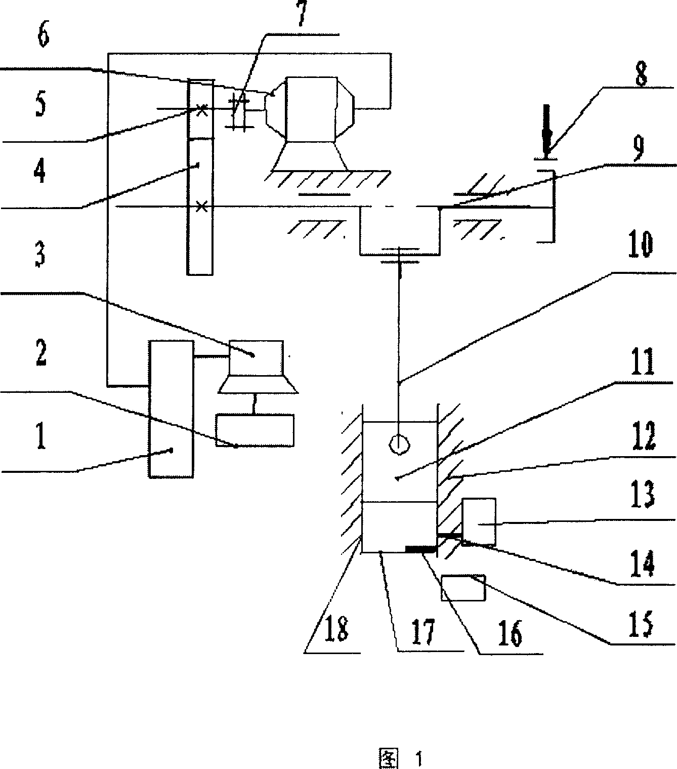
[0023] As shown in Figure 1, the switched reluctance speed regulating motor 6 is installed on the fuselage 12, the output shaft is connected with the pinion 5 through the coupling 7, the pinion 5 is meshed with the large gear / flywheel 4 for transmission, and the large gear / flywheel The flywheel 4 is combined with the crankshaft 9, the brake 8 is installed on the crankshaft 9, the crankshaft 9 is installed on the fuselage through bearings, the crank neck of the crankshaft 9 is equipped with a connecting rod 10, and the connecting rod 10 is connected to the slider through a ball joint or a cylindrical pin. The 11 phases are connected, the guide rail 18 is installed symmetrically with the central axis in the fuselage 12, the slider 11 is slidingly matched with the guide rail 18, the load cell 16 is installed in the workbench 17, and the infrared pyroelectric sensor 14 is installed in the fuselage 12 in the work dangerous area superior.
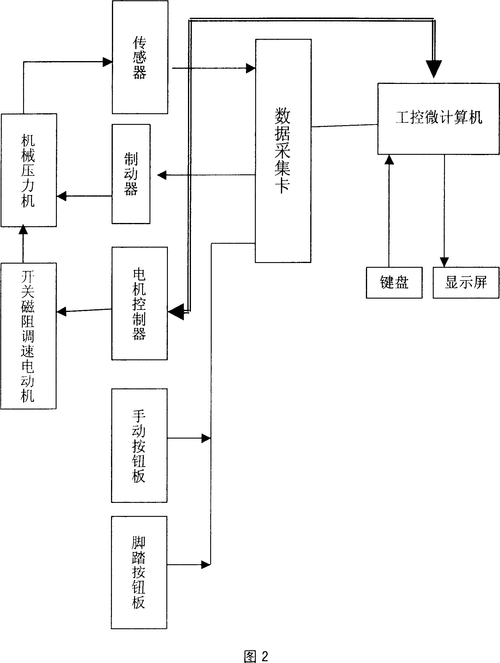
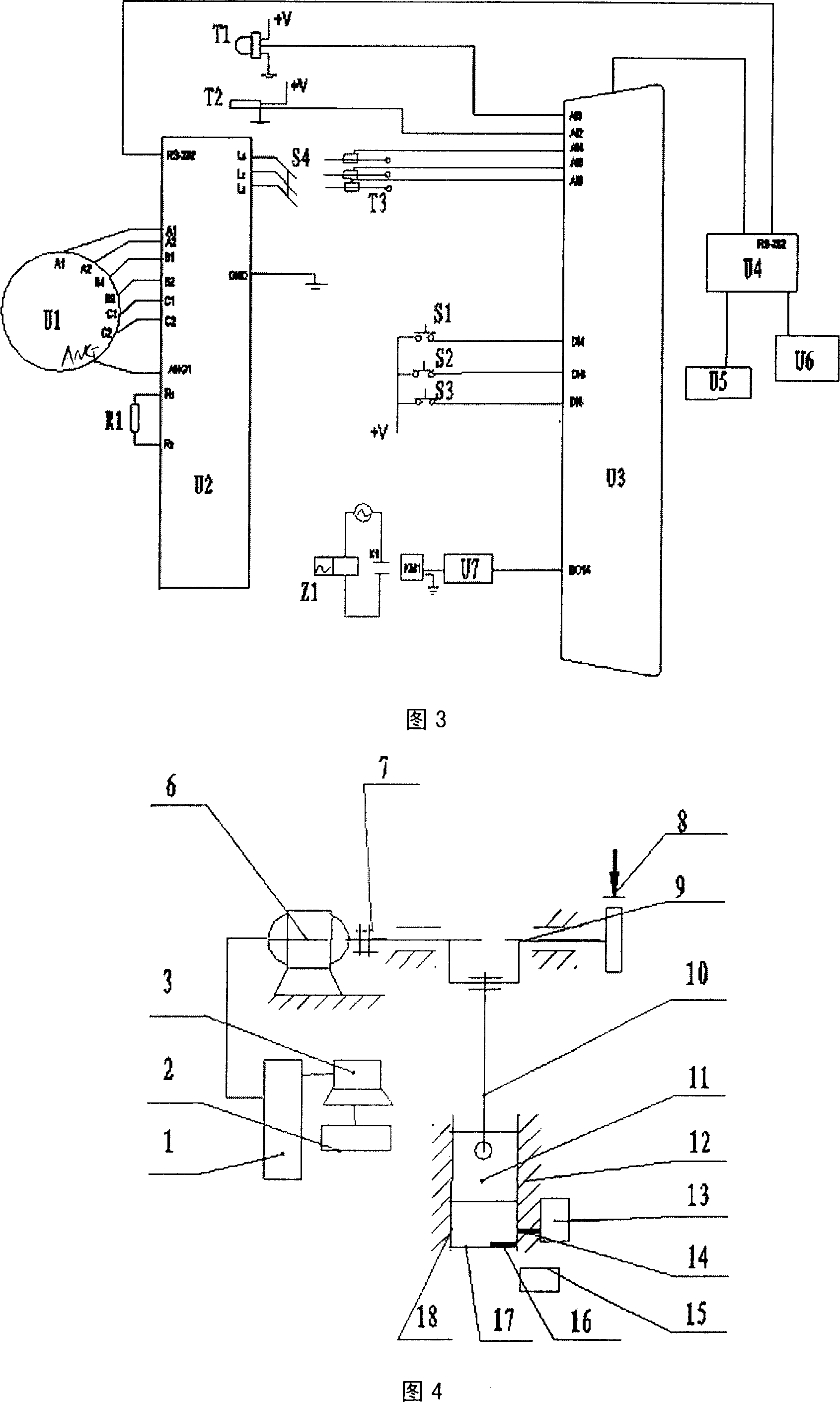
[0024] As shown in Figure 2, the industria...
Embodiment 2
[0028] As shown in Figure 4, the transmission mechanism can also be installed on the fuselage 12 by a switched reluctance speed regulating motor 6, the output shaft is connected to the crankshaft 9 through a coupling 7, the brake 8 is installed on the crankshaft 9, and the crankshaft 9 is installed on the machine body through a bearing. On the body 12, a connecting rod 10 is installed on the crank neck of the crankshaft 9, and the connecting rod 10 is connected with the slider 11. A guide rail 18 is installed symmetrically with the central axis in the fuselage 12, and the slider 11 is slidably matched with the guide rail 18. The load cell 16 is installed on the workbench 17, and the infrared pyroelectric sensor 14 is installed on the fuselage 12 of the working danger zone.
Embodiment 3
[0030] As shown in Figure 5, the transmission mechanism can also be installed on the mechanical press machine body 12 with a switched reluctance speed regulating motor 6, the output shaft is connected with the pinion 5 through a coupling 7, and the pinion and the large gear / flywheel 4 Mesh transmission, the large gear / flywheel 4 is installed on the fixed shaft 19, the brake 8 is installed on the shaft 9, the shaft 9 is installed on the fuselage 12 through the bearing, and the connecting rod 10 is installed on the eccentric neck of the large gear 4, and the connecting rod 10 and the The slide block 11 is connected, and the guide rail 18 is installed symmetrically with the central axis in the fuselage 12. The slide block 11 is slidably matched with the guide rail 18, the load cell 16 is installed on the workbench 17, and the infrared pyroelectric sensor 14 is installed on the machine in the work dangerous area. 12 on the body.
[0031] Brake 8 can select simple belt brake for us...
PUM
 Abstract
Description
Claims
Application Information
 - R&D
- Intellectual Property
- Life Sciences
- Materials
- Tech Scout
- Unparalleled Data Quality
- Higher Quality Content
- 60% Fewer Hallucinations
Browse by: Latest US Patents, China's latest patents, Technical Efficacy Thesaurus, Application Domain, Technology Topic, Popular Technical Reports.
© 2025 PatSnap. All rights reserved.Legal|Privacy policy|Modern Slavery Act Transparency Statement|Sitemap|About US| Contact US: help@patsnap.com


