
Rare earth permanent-magnet synchronization motor with mouse cage type magnetic force regulating sleeve

A rare-earth permanent magnet and synchronous motor technology, applied in the direction of synchronous machine components, etc., can solve the problems of reduced efficiency, reduced magnetic field strength of permanent magnets, and difficult adjustment of magnetic force, so as to save electric energy, solve start-up difficulties, and have obvious energy-saving effects Effect

Inactive Publication Date: 2007-05-23
邓传义
View PDF0 Cites 3 Cited by
  • Summary
  • Abstract
  • Description
  • Claims
  • Application Information

AI Technical Summary

Problems solved by technology

However, due to the high magnetic field strength of this permanent magnet material, it is difficult to optimize the air gap between the rotor and the stator of the motor using this type of permanent magnet material, and it is also difficult to adjust the magnetic force, which makes it difficult to start the motor.
For this reason, I researched out in 2004 between the stator and the rotor in the motor, the air gap adjustment sleeve (seeing Chinese patent 2004100468889) that a non-magnetic material is made additionally is installed this scheme, has solved the difficulty of starting the motor However, since the air gap adjustment sleeve used is made of non-magnetic material, it has a certain barrier effect on the magnetic field and reduces the magnetic field strength of the permanent magnet to do work, so that the motor generates a large amount of heat during operation and the temperature rises Higher and faster; at the same time, its efficiency is lower than that of existing similar motors
Therefore, in 2006, I researched the scheme of using magnetically conductive material to make the air gap adjustment sleeve (see Chinese patent 2006100320787), which solved the problem of high heat generation, and its energy-saving effect is also very obvious, but it is different from the theory Compared with the efficiency, there is still a certain gap

Method used


Image

  • Rare earth permanent-magnet synchronization motor with mouse cage type magnetic force regulating sleeve
  • Rare earth permanent-magnet synchronization motor with mouse cage type magnetic force regulating sleeve

Examples


Embodiment Construction

[0010] Embodiments of the present invention will be described in detail below in conjunction with the accompanying drawings.

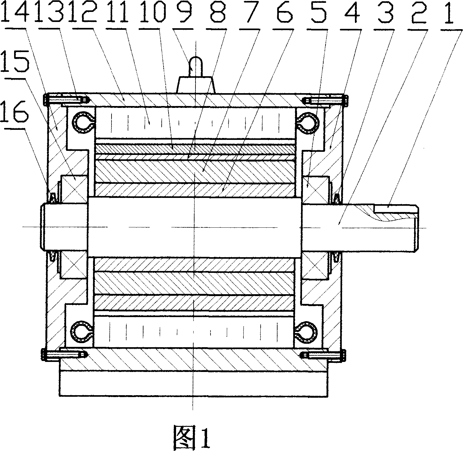
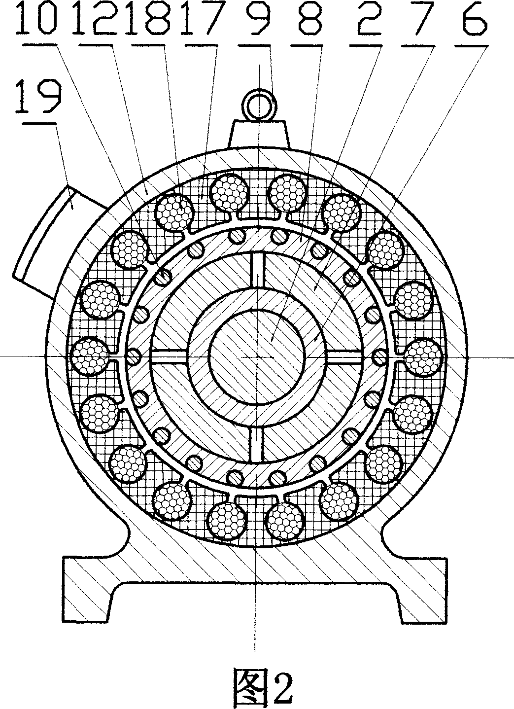
[0011] Present embodiment is made up of motor shaft (2), sleeve (6), stator casing (12), stator winding (11), left and right end covers (14) and ( 4) and permanent magnet (7) and magnetic force adjustment cover (8) constitute.

[0012] The stator housing (12) is a cylindrical body with a base at its lower part, a suspension ring (9) in the middle of the upper part, and a stator winding (11) installed on the inner wall of the cylindrical body. There is a power input box (19) for the stator winding (11). The stator winding (11) includes a winding coil (18) and a winding yoke (17), the winding coil (18) is embedded in the slot of the winding yoke (17), and the winding yoke (17) is fixed in the cylinder of the stator housing (12) on the wall. The power cord is introduced by the power input wire box (19), and is connected with the winding coil (18).

[...


PUM


Abstract

The invention relates to a rare-earth permanent magnetic synchronous motor mounted with mouse mill magnetic force adjuster sheath, wherein it is formed by motor axle (2), muffle (6), stator frame (12), stator winding (11), left and right end covers (14, 4) with left and right bearings (15, 5), permanent magnet (7) and magnetic force adjusting sheath (8). The invention has simple structure and energy saving property, with wide application.

Description

technical field [0001] The invention relates to a permanent magnet direct current motor, in particular to a rare earth permanent magnet synchronous motor equipped with a squirrel-cage magnetic adjustment sleeve. Background technique [0002] In the prior art, the rare earth permanent magnet synchronous motor made of rare earth NdFeB permanent magnet material with high performance and high magnetic field strength (the magnetic field strength can reach 4000 gauss), compared with the double winding DC synchronous motor, its energy saving effect is very significant . However, since the magnetic field strength of this permanent magnet material is too high, it is difficult to optimize the air gap between the rotor and the stator of the motor using this type of permanent magnet material, and it is also difficult to adjust the magnitude of the magnetic force, resulting in difficulty in starting the motor. For this reason, I researched out in 2004 between the stator and the rotor in...

Claims


Application Information

Patent Timeline
Patent Type & Authority Applications(China)
IPC IPC(8): H02K21/02
Inventor 邓传义李宝生张升平欧见宝邹月英肖建群周辉英欧利平朱士庭唐祥民
Owner 邓传义
Learn More