
Automatic frequency-hopping remote controller

A remote control device, an automatic technology, applied in the directions of remote control tuning using near-field transmission, remote control tuning using radio transmission, signal transmission systems, etc., can solve problems such as remote control channel signal interference

Inactive Publication Date: 2007-05-23
TOPSEED TECH
View PDF0 Cites 13 Cited by
  • Summary
  • Abstract
  • Description
  • Claims
  • Application Information

AI Technical Summary

Problems solved by technology

[0008] Another object of the present invention is to simultaneously solve the channel signal interference problem of the remote controller

Method used


Image

  • Automatic frequency-hopping remote controller
  • Automatic frequency-hopping remote controller
  • Automatic frequency-hopping remote controller

Examples


Embodiment Construction

[0024] The technical content, features and effects of the present invention will become apparent after the preferred embodiments of the present invention are described in detail below in conjunction with the accompanying drawings.

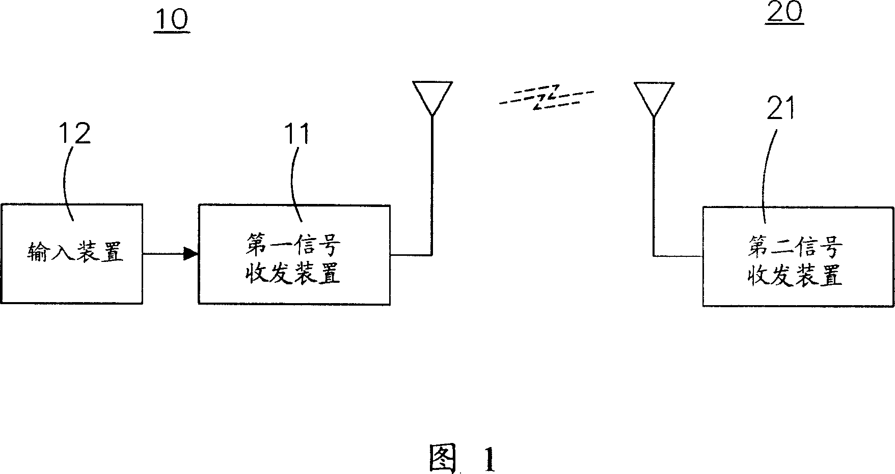
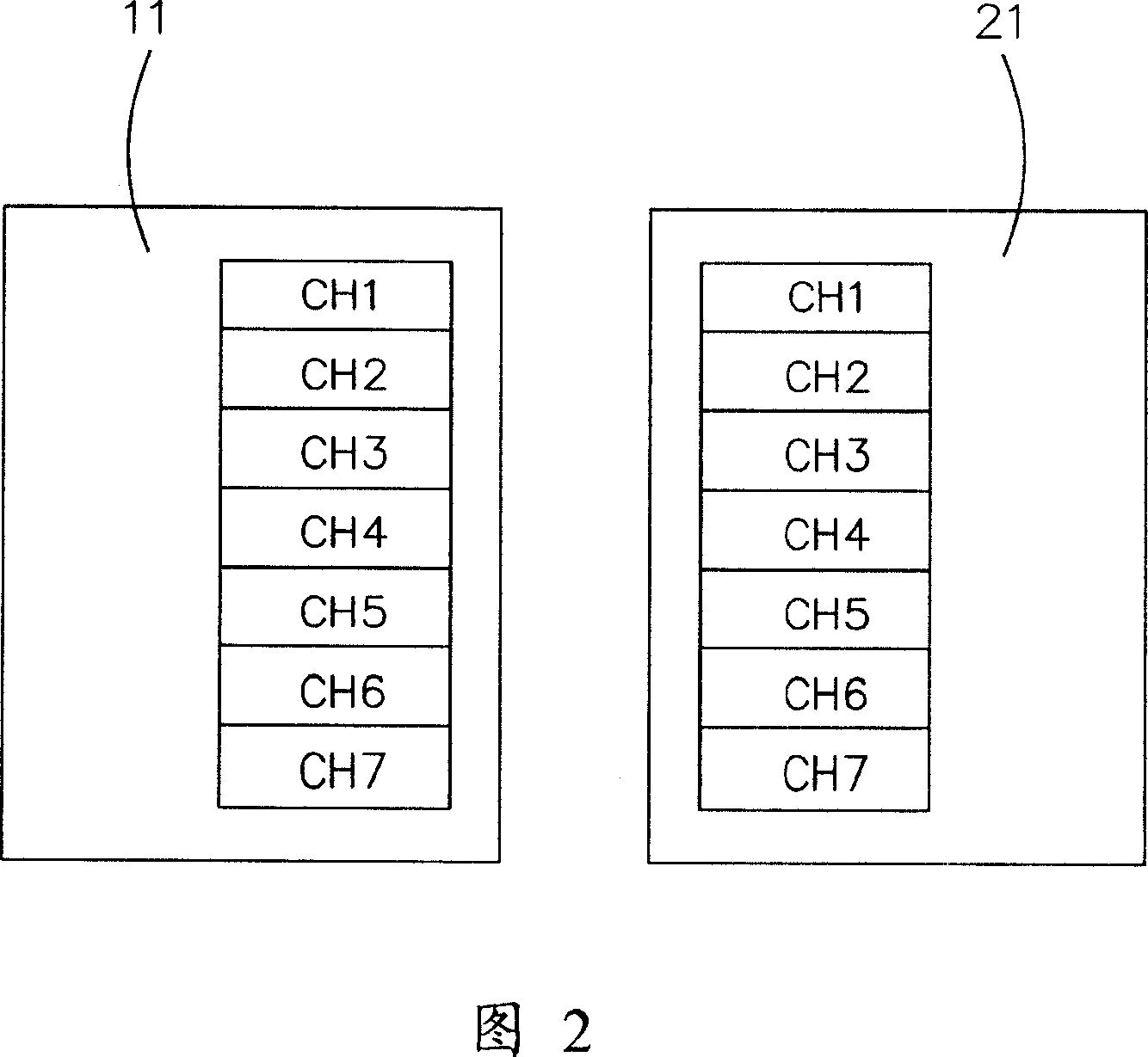
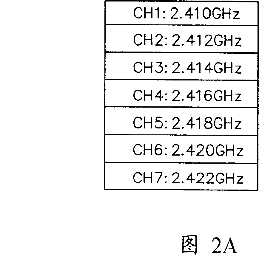
[0025] Fig. 1 is a basic block diagram of the present invention in one-to-one control mode. The remote control device of the present invention is composed of corresponding sending end 10 and receiving end 20 . The sending end 10 is usually a remote controller, including a first signal transceiving device 11 capable of transmitting multiple channels, and an input device 12 . The trigger command of the input device 12 transmits the remote control signal with the preset channel. The sending end 10 can also receive signals of another fixed channel transmitted by other ends, and then switch the channel of the radio frequency signal transmitted by the external operation trigger signal, and then transmit the remote control signal on this channel next tim...


PUM


Abstract

An automatic frequency-hopping remote control device, when the remote control signal is disturbed during transmission, it automatically makes transduction. The remote control device comprises the corresponding transmitter and receiver, and the transmitter has the first signal transceiver device and input device with a number of channels issuing functions, and issues a remote control signal from the pre-set channel, by the trigger command of the input device. The receiver is the second signal transceiver device located on the electronic equipment, which can receive the remote control signal from the transmitter, and evaluates the received signal quality, and if the signal quality is poor, automatically switches to another receiving channel, and sends a transduction signal to the transmitter, to switch the transmitter to the corresponding channel also, and the next launch of the remote control signal also uses this channel.

Description

technical field [0001] The invention relates to a wireless remote control frequency hopping device, in particular to a radio frequency (RF) remote control device capable of automatic frequency hopping. Background technique [0002] There are many applications of remote controllers, such as the control of projection equipment, video recorders, and televisions, among which the application of infrared signal transmission technology is more common. However, the environment that infrared rays are suitable for is usually a small, closed area. For control with low requirements and short distances, infrared transmission is a good choice, but relatively speaking, it also has its disadvantages: infrared transmission is easily affected by distance restrictions and obstructions. [0003] Specifically, infrared is a low-cost means of wireless transmission. Infrared rays send signals to the front with a narrow fan angle (about 60 degrees), because infrared rays have a long wavelength, m...

Claims


Application Information

Patent Timeline
IPC IPC(8): G08C17/02H03J9/02
Inventor 姬中平
Owner TOPSEED TECH
Learn More