
High-pressure homogeneous device

A high-pressure homogeneous and structural technology, applied in the fields of dissolution, mixers, chemical instruments and methods, etc.

Active Publication Date: 2007-05-09
IND TECH RES INST
View PDF0 Cites 5 Cited by
  • Summary
  • Abstract
  • Description
  • Claims
  • Application Information

AI Technical Summary

Problems solved by technology

[0006] Although the technology disclosed in this Japanese patent has improved the three-piece structure disclosed in the above-mentioned U.S. patent into a two-piece structure that is easier to process and assemble, it must be manufactured separately on each inflow carrier and outlet carrier. On the platform, the straight grooves and horizontal grooves are processed separately, and the direction used to guide the high-pressure mixed liquid to impact each other is constant, and it is not suitable for occasions that require impact and reaction at different angles.

Method used


Image

  • High-pressure homogeneous device
  • High-pressure homogeneous device
  • High-pressure homogeneous device

Examples


Embodiment Construction

[0028] In order to make the above-mentioned structures, features and functions of the present invention more comprehensible, several preferred embodiments are given and further described in detail as follows in conjunction with the accompanying drawings.

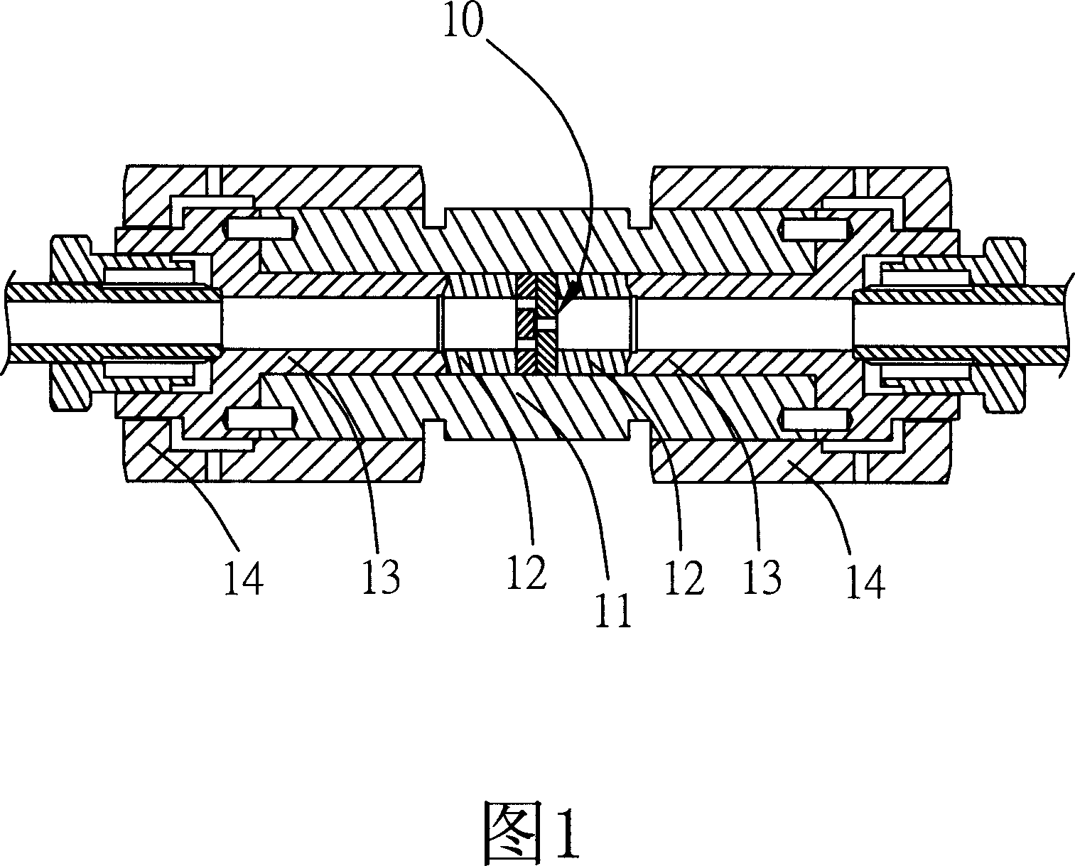
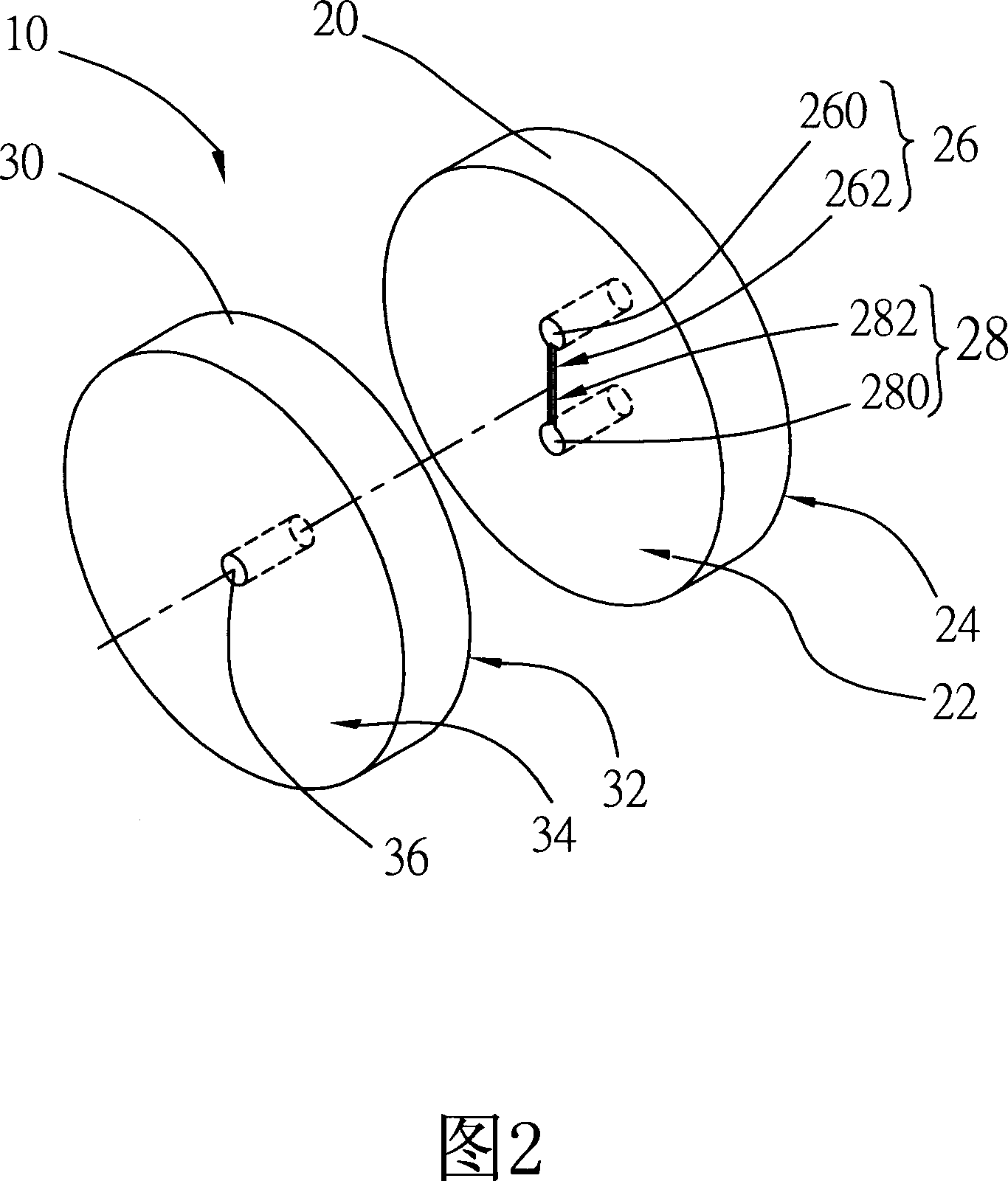
[0029] Firstly please refer to FIGS. 1 and 2 , the flow guiding structure 10 disclosed in the present invention is composed of an inlet component 20 and an outlet component 30 that can be closely combined with each other. When in use, it is placed in a tubular positioning assembly 11, the two ends of which are respectively supported by a sleeve 12 and a connecting piece 13, and the two ends of the positioning assembly 11 are respectively provided with a locking assembly 14 for Each sleeve pipe 12 and connector 13 are pressed against each other by two ends.

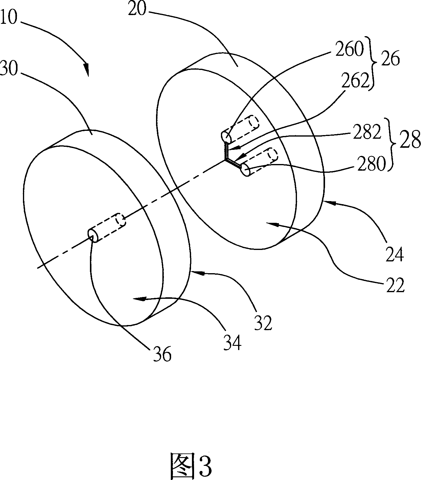
[0030] The introduction assembly 20 has: a first inner end surface 22 and a first outer end surface 24, at least two inflow units (26, 28) are arranged at the central pa...


PUM


Abstract

A high-pressure homogenizing mechanism has a leading-in module with the first internal end face and the first external end face, at least two flow-in units arranged at the predefined positions of said leading-in module and with an inlet hole between said internal and external end faces and a guide slot on said internal end face, a leading-out module with the second internal end face and the second external end face, and at least one flow-out unit between said second internal and external end faces and communicated with the predefined position of said flow-in unit.

Description

technical field [0001] The invention relates to a high-pressure homogenization device, in particular to a diversion structure of a high-pressure homogenization device having flow channels with various relative angles to improve its applicability and efficiency. Background technique [0002] The high pressure homogenizer (High Pressure Homogenizer) referred to below in the present invention refers to the use of a high pressure pump to pressurize the mixed liquid to a specific pressure, and use a high pressure pipeline to transport the mixed liquid to a homogenizing valve (Homogenizing Valve). ), and through the reduction design of the cross-sectional area of ​​the flow channel of the homogenizing valve, the original high-pressure mixed liquid is converted into a high-speed mixed liquid (the flow rate can reach 600m / s), and when two high-speed mixed liquids meet, the The impact force, shear force, cavitation and pressure reduction effects generated by the machine can be used f...

Claims


Application Information

Patent Timeline
Patent Type & Authority Applications(China)
IPC IPC(8): B01F5/06
Inventor 周大鑫徐绍煜苏志杰
Owner IND TECH RES INST
Learn More