
Sealing structure of discharge lamp

A sealing structure and technology for discharge lamps, which are applied in the fields of discharge lamps, discharge tube/lamp manufacturing, gas discharge lamp parts, etc., can solve problems such as reduced work efficiency and difficulty in welding and winding foils.

Active Publication Date: 2007-04-25
ORC MFG
View PDF1 Cites 11 Cited by
  • Summary
  • Abstract
  • Description
  • Claims
  • Application Information

AI Technical Summary

Problems solved by technology

The work of welding wound foil is very difficult, resulting in a significant decrease in work efficiency

Method used


Image

  • Sealing structure of discharge lamp
  • Sealing structure of discharge lamp
  • Sealing structure of discharge lamp

Examples


Embodiment Construction

[0029] The best mode for carrying out the present invention will be described below with reference to FIGS. 1 to 10 .

[0030] 【Example】

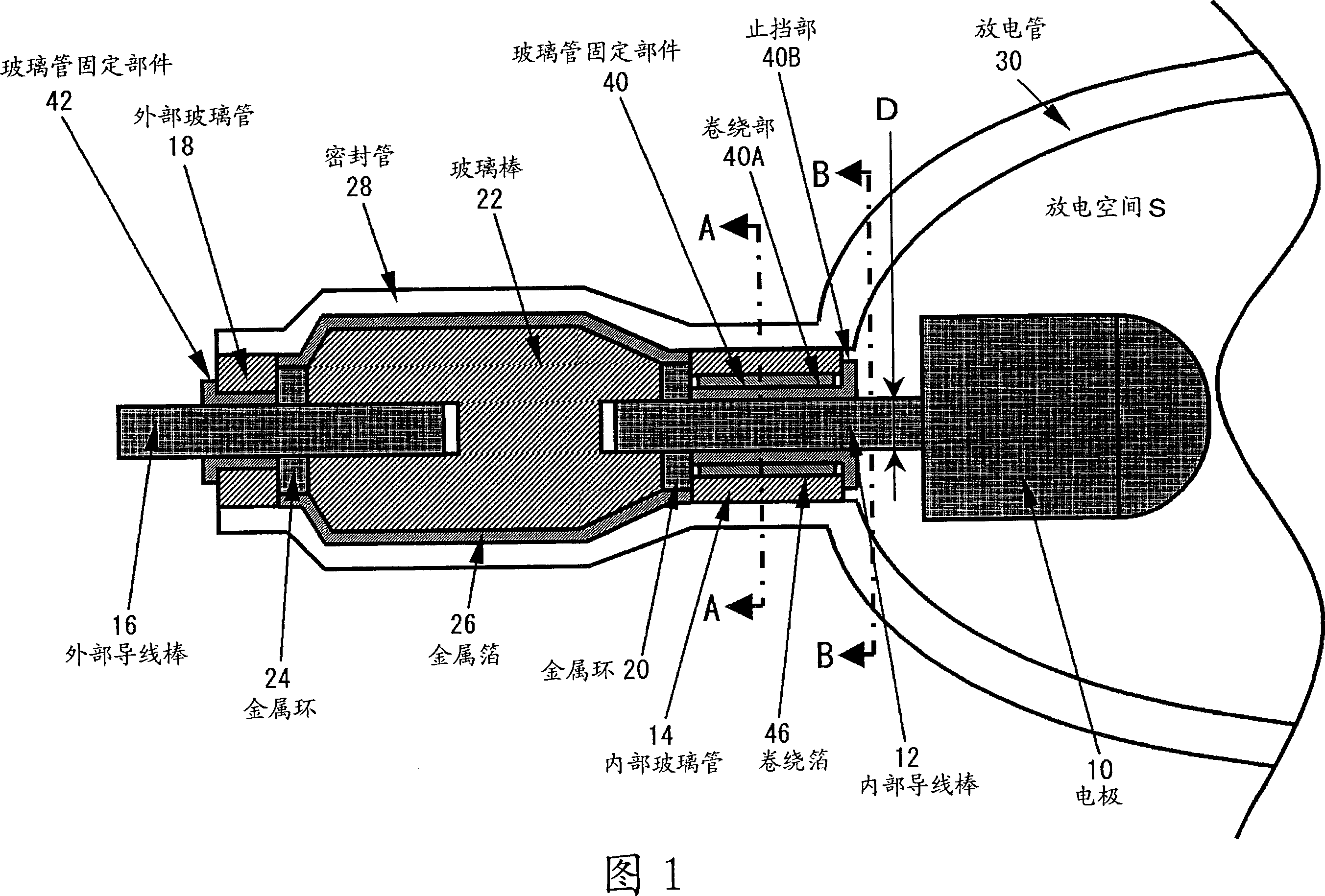
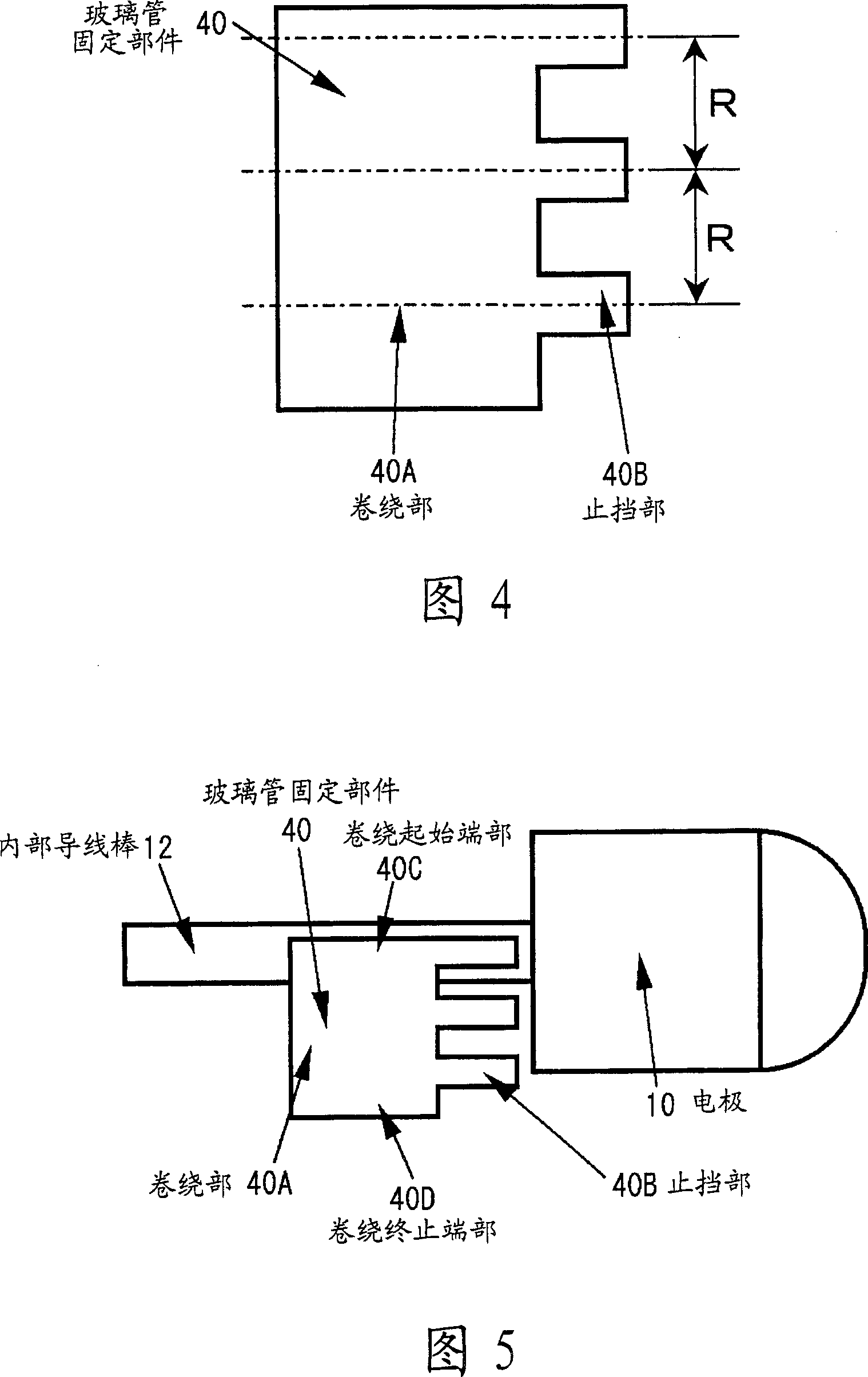
[0031] In the sealing part of the discharge lamp according to the embodiment of the present invention, the winding part of the glass tube fixing member is wound around the circumferential surface of the lead rod of the electrode, and the lead rod is inserted into the cylindrical glass tube and protrudes from the end surface of the glass tube. The extended portion of the coiling portion is bent to become a stopper that restrains the glass tube from moving along the tube axis.

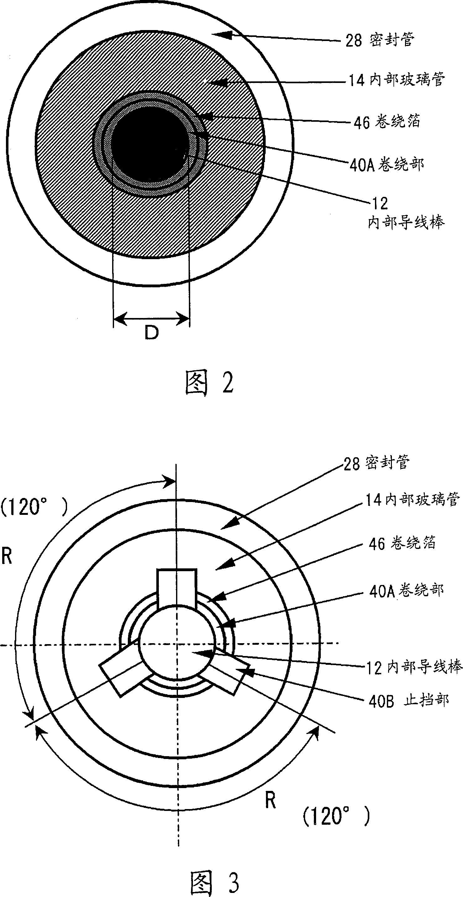
[0032]Fig. 1 is a sectional view along the axis of a sealing portion of a discharge lamp in an embodiment of the present invention. As an example, a sealing portion of a short-arc discharge lamp is shown. Fig. 2 is a sectional view along A-A of Fig. 1 . Fig. 3 is a B-B sectional view of Fig. 1 . In FIG. 1 , FIG. 2 and FIG. 3 , the discharge space S is filled with ...


PUM


Abstract

The present invention provides a sealing structure of discharge lamp which accurately mounts the installing component on the discharge tube with high efficiency in the assembly procedure of the sealing discharge lamp. The circle surface of the interior conductor rod (12) in the electrode (10) is winded with a glass tube fixing component (40). The interior conductor rod (12) is inserted into the cylindraceous interior glass tube (14). A linguiform stopping component (40B) is extended from the winding component (40A) of the glass tube fixing component (40). Curving the stopping component (40B) which is projecting in the end of the interior glass tube (14) prevents the movement of the interior glass tube (14) along the tube axial direction. A winding foil which has same axis with the interior conductor rod (12) is arranged between the winding component (40A) and the interior glass tube (14). The glass tube fixing component (40) comprises an arbitrary components selected from the group of Ta, Nb, W, and Mo. The winding component (40A) contains Ta or Nb, and the winding foil contains an arbitrary component of Ta, Nb, W, and Mo.

Description

technical field [0001] The present invention relates to a sealing structure of a discharge lamp, and particularly to a sealing structure capable of accurately and efficiently assembling a discharge lamp mounting portion. Background technique [0002] In a discharge lamp such as a short-arc discharge lamp, a discharge tube in which a discharge gas such as mercury or a rare gas is enclosed has a pair of electrodes supported by an inner lead bar. The inner wire rod is supported by the glass tube of the sealing part and the inner glass tube. Electrodes and internal lead rods and internal glass tubes constitute the mounting portion. In the step of attaching the mounting portion to the discharge tube, the sealing tube is heated and shrunk using a gas burner to perform sealing. At this time, a gap is created between the inner glass tube and the inner wire rod. Although an extremely small gap is necessary, if the gap is too large, the seal may be broken and the internal lead bar ...

Claims


Application Information

Patent Timeline
Patent Type & Authority Applications(China)
IPC IPC(8): H01J61/36
CPCH01J9/266H01J61/361H01J61/365H01J61/366H01J2209/26
Inventor 林武弘仓野正弘
Owner ORC MFG
Learn More