
Coating apparatus

A coating device and coating technology, applied to the surface coating liquid device, coating, optics, etc., can solve the problems of easy vibration, uneven coating of alignment film materials, and removal of blades 16, etc., to achieve The effect of reducing the incidence

Inactive Publication Date: 2007-04-25
AU OPTRONICS CORP
View PDF0 Cites 2 Cited by
  • Summary
  • Abstract
  • Description
  • Claims
  • Application Information

AI Technical Summary

Problems solved by technology

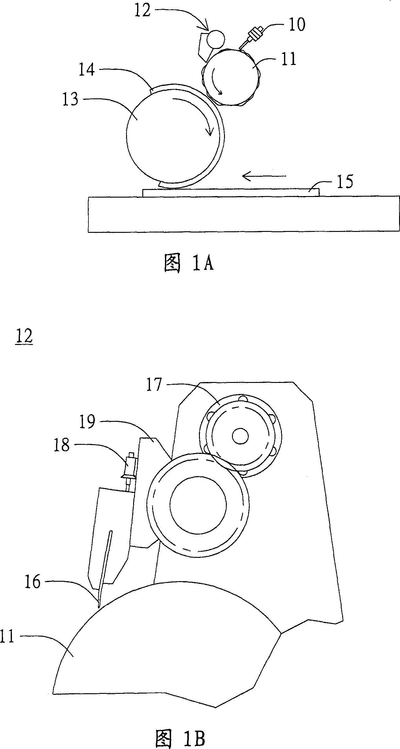
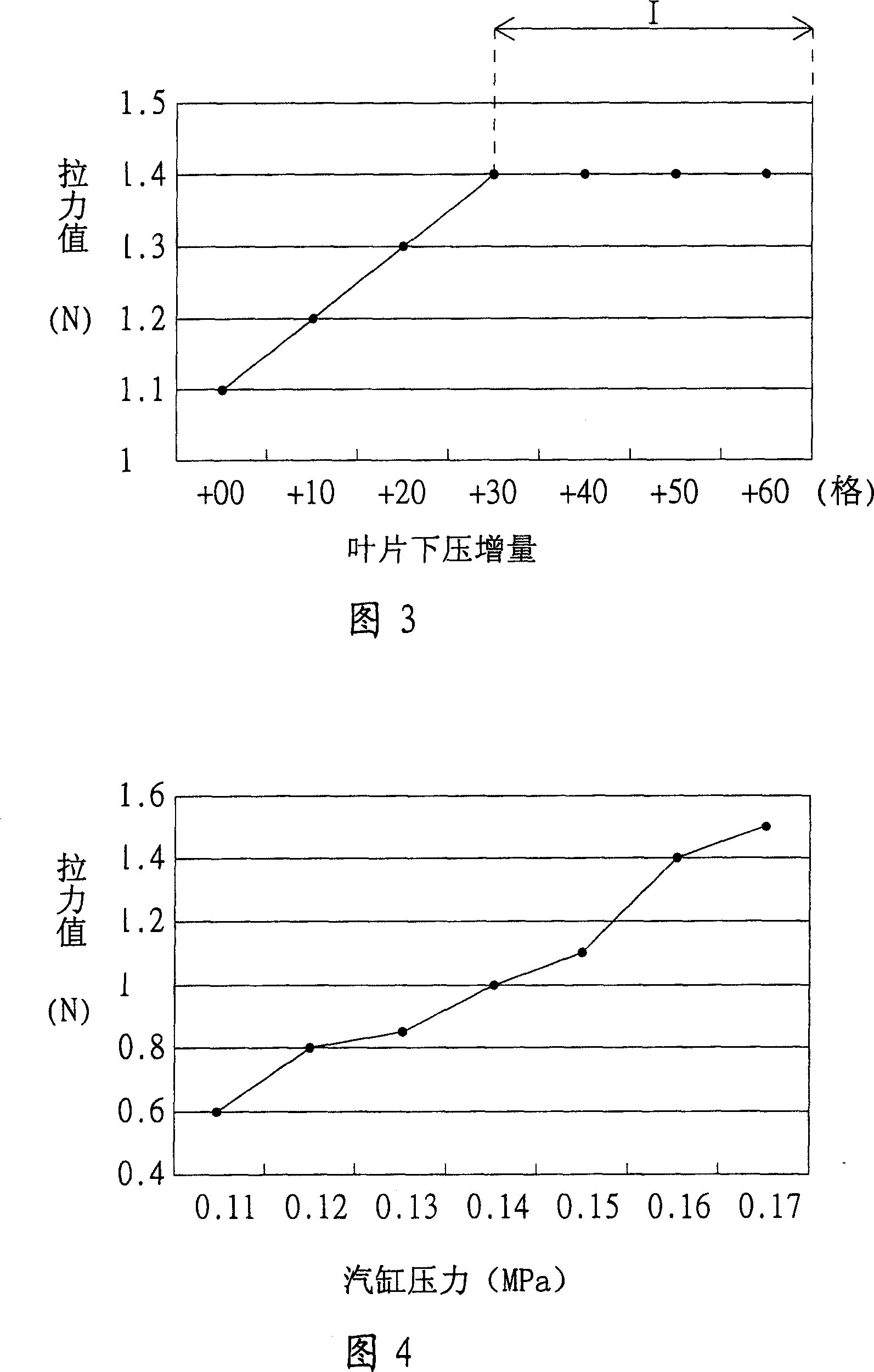
[0009] As shown in Table 2, the cylinder pressure required to lift the vane 16 is about 0.14-0.16 MPa, while the reduced cylinder pressure (about 0.025 MPa) in order to meet the requirements of the pulling force (about 1.3-1.4 N) is far less than 0.14 MPa, the rotating cylinder 17 will not be able to remove the blade 16 from the printing wheel 11 smoothly
[0010] Furthermore, since the material of the printing wheel 11 is usually ceramics, and the material of the blade 16 is usually plastic, when the pressing force of the blade 16 is too large, it is very easy to cause the wear of the blade 16 and transfer the abrasive of the blade 16 to the substrate. 15 up, so that defective products increase
In addition, when the blade 16 has insufficient downward pressure and the distance between the blade 16 and the printing wheel 11 is too large, vibrations are likely to occur between the blade 16, the printing wheel 11, or other parts on the machine, which will cause uneven coating of the alignment film material and cause Defects

Method used


Image

  • Coating apparatus
  • Coating apparatus
  • Coating apparatus

Examples


Embodiment Construction

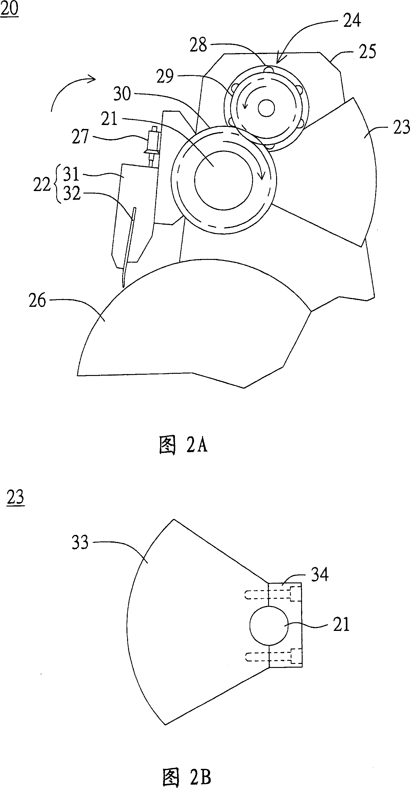
[0054] Please refer to FIG. 2A , which is a schematic diagram of a coating device according to a preferred embodiment of the present invention. As shown in FIG. 2A , the coating device 20 includes a rotating shaft 21 , a coating unit 22 , a counterweight unit 23 and a driving unit 24 . The rotating shaft 21 is arranged on a device base frame 25 and can rotate relative to the device base frame 25 . The coating unit 22 is fixed on the rotating shaft 21 and can rotate along with the rotating shaft 21 . The counterweight unit 23 is rotatably disposed on the rotating shaft 21 and is located on two sides of the rotating shaft 21 with the coating unit 22 respectively. The counterweight unit 23 is used to balance the weight of the coating unit 22 . The driving unit 24 is coupled to the rotating shaft 21 to drive the rotating shaft 21 to rotate, thereby adjusting the distance between the coating unit 22 and a printing wheel 26 and adjusting the pressing force of the coating unit 22 on ...


PUM


Abstract

This invention relates to a coating device applied to control thickness of coating on print wheel, which comprises rotation axis, match unit and drive unit, wherein, the rotation axis is set with one coat unit; the match unit is to match rotation axis by rotation type located on both sides of coat unit; the match unit is to balance coat unit weight; the drive unit is coupled to rotation axis to drive rotation axis to adjust coat unit and print wheel distance.

Description

technical field [0001] The invention relates to a coating device, in particular to a coating device with the function of controlling the thickness of coating materials. Background technique [0002] The substrate of the liquid crystal display panel must undergo an alignment process in order to provide the required alignment and pre-tilt substrate for the liquid crystal molecules in the panel. In the alignment process, a layer of alignment film is first produced on the substrate, and then groove-like traces are brushed on the alignment film in order to make the liquid crystal molecules tilt in a certain direction and angle. Therefore, the film thickness and uniformity of the film thickness of the alignment film are very important. [0003] Please refer to FIGS. 1A-1B . FIG. 1A is a schematic diagram of an alignment film printing process of a conventional liquid crystal display panel, and FIG. 1B is a schematic diagram of the coating device in FIG. 1A . As shown in Figure 1A...

Claims


Application Information

Patent Timeline
Patent Type & Authority Applications(China)
IPC IPC(8): G02F1/1337G02F1/1333B05C1/00
Inventor 洪二郎
Owner AU OPTRONICS CORP
Learn More