
Flicker detection for image sensing devices

A technology of wireless communication device and geographic location, applied in the field of image processing, can solve problems such as non-existence detection and avoiding flickering problems

Inactive Publication Date: 2007-04-11
QUALCOMM INC
View PDF0 Cites 35 Cited by
  • Summary
  • Abstract
  • Description
  • Claims
  • Application Information

AI Technical Summary

Problems solved by technology

Currently there is no mechanism that allows camera systems to detect and avoid flickering problems without user intervention

Method used


Image

  • Flicker detection for image sensing devices
  • Flicker detection for image sensing devices
  • Flicker detection for image sensing devices

Examples


Embodiment Construction

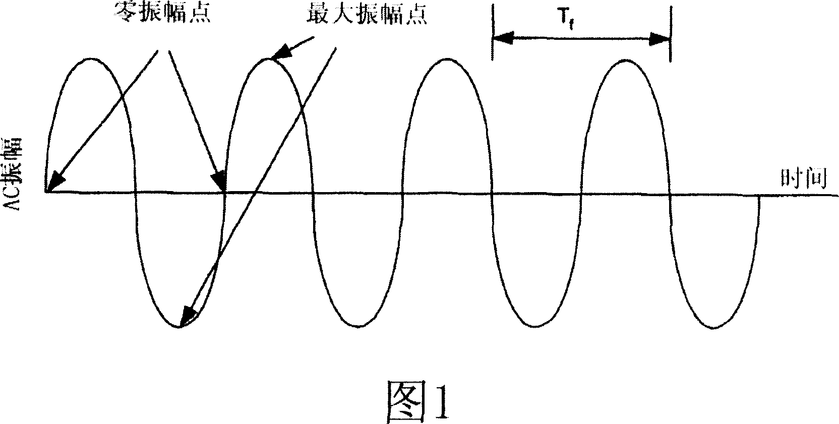
[0021] Figure 1 is for a period with a T f A representation of a sine AC wave. As previously discussed, the zero crossings of the sinusoidal AC wave correspond to reduced light intensity in fluorescent lighting conditions, which adversely affects the image detected by the sensor in the camera system. A solution exists for avoiding this "flicker" problem, whereby the rolling shutter is limited to exposure times that are multiples of the AC period. However, this solution is limited because it requires manual user intervention whenever the camera is shifted between regions of different AC cycles.

[0022] Embodiments described herein are for automatically setting the exposure time of a rolling shutter using certain technical features of a wireless communication device.

[0023] 2 is a block diagram of a camera system incorporated into a wireless communication device. Wireless communication device 10 may comprise a cellular telephone, a personal digital assistant (PDA), or a mo...


PUM


Abstract

Camera systems are presented that can utilize geographical information to detect and avoid flicker conditions caused by fluorescent lighting automatically. The camera systems are configured to work in conjunction with signals from wireless communication networks or the GPS system.

Description

[0001] This application claims priority to US Provisional Application No. 60 / 564,668, filed April 21, 2004, which is hereby incorporated by reference in its entirety. technical field [0002] The present invention is directed to image processing, and in particular to image sensing. Background technique [0003] In many camera systems, image sensing is performed using an electronic "rolling shutter," which is an exposure mechanism that exposes pixels within an image sensor array, usually on a row-by-row basis. The duration of the exposure is programmable so that the exposure can range from partial row durations, individual row durations, or any value up to and including the full image frame duration. [0004] Due to the nature of the rolling shutter, the pixel lines of one image segment may be exposed under different lighting conditions than the pixel lines of another image segment because each segment is exposed at a different time. Under daylight or incandescent lighting c...

Claims


Application Information

Patent Timeline
IPC IPC(8): H04N5/225
Inventor 本尼·卡提比安阿南塔帕德马纳卜汉·A·坎达哈达伊
Owner QUALCOMM INC
Learn More