Floating pipe type falling water noise reducing support frame

A support frame and floating tube technology, which is applied in the direction of sounding equipment and instruments, can solve the problems of different buoyancy, loud noise, unreasonable design of the buoyant support frame, etc., and achieves stable distance, uniform buoyancy, and good levelness. Effect

Inactive Publication Date: 2007-04-11
常州金坛塑料厂
View PDF1 Cites 0 Cited by
  • Summary
  • Abstract
  • Description
  • Claims
  • Application Information

AI Technical Summary

Problems solved by technology

This kind of falling water noise reducer has become the first choice for noise reduction of cooling towers in power plants today, but there are still some defects in the actual use of this product, among which the design of the buoy type support frame is not reasonable enough, and the grille On the FRP buoy, due to the large and small FRP buoys, the buoyancy generated by each buoy is different. A

Method used


Image

  • Floating pipe type falling water noise reducing support frame
  • Floating pipe type falling water noise reducing support frame
  • Floating pipe type falling water noise reducing support frame

Examples


example 1

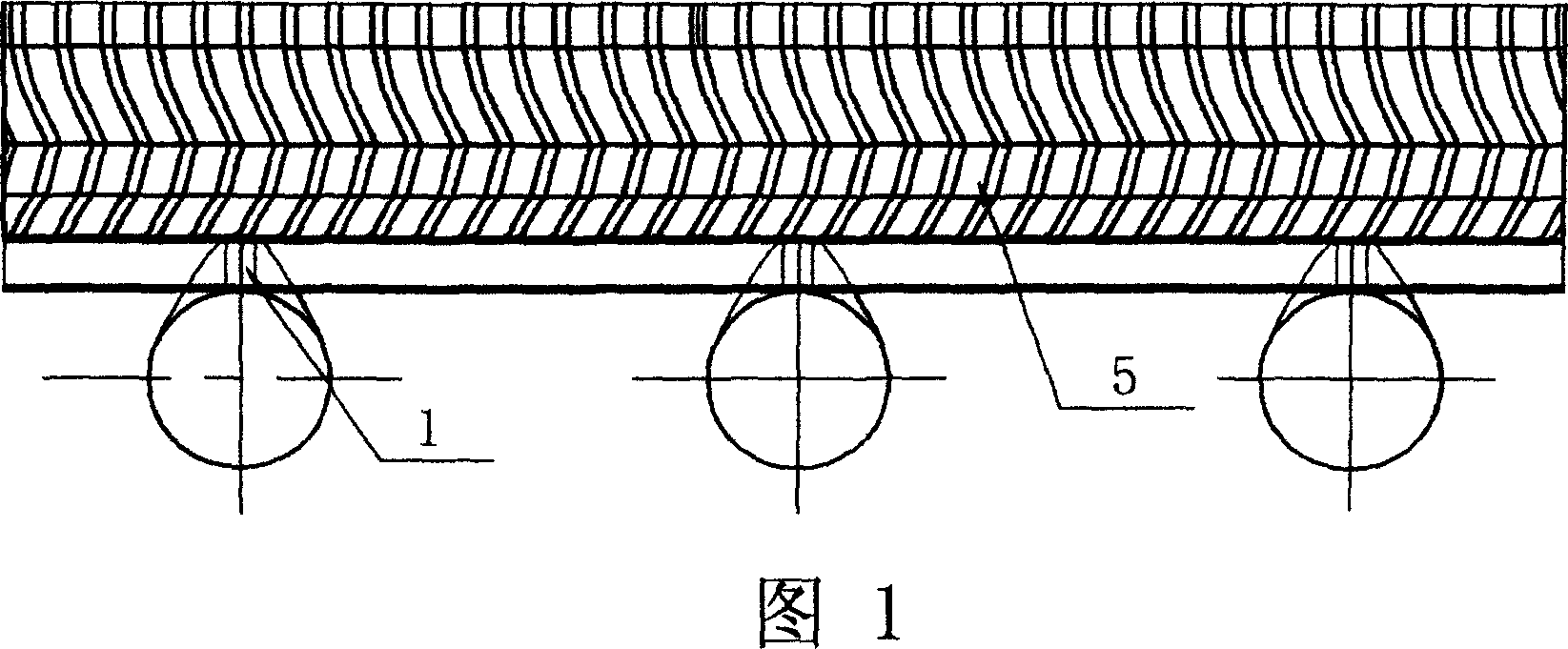
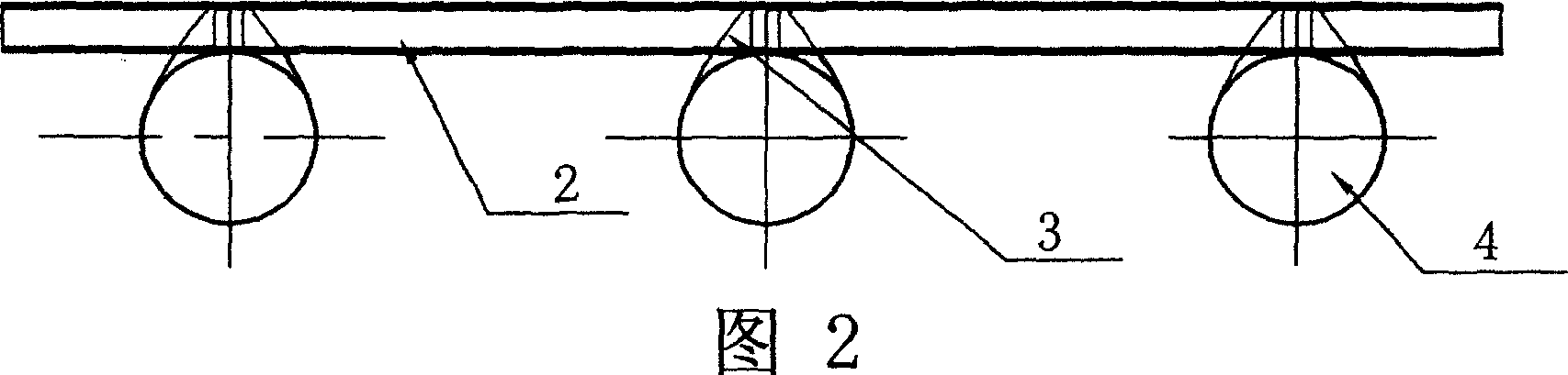
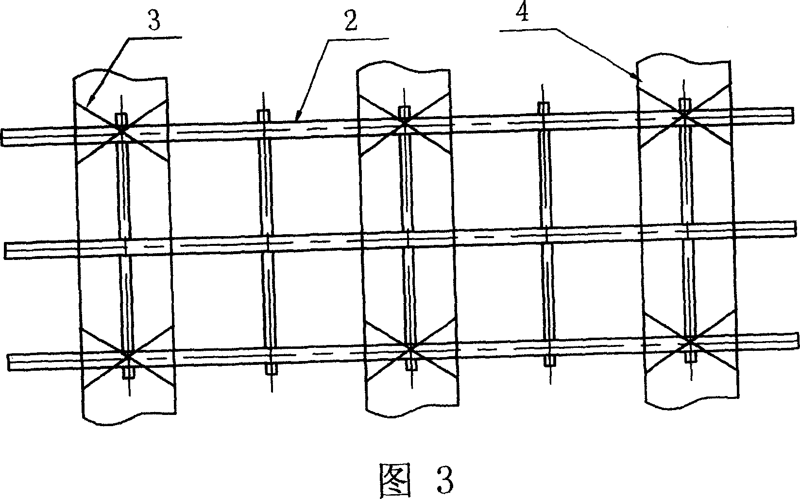
[0014] Example 1: The floating pipe falling into the water noise reduction support frame, as shown in Figures 2 and 3, it consists of a grille frame 2, a fastening belt 3 and a floating frame 1, and the floating frame 1 is composed of several circular The hollow floating tubes 4 are arranged and combined in parallel intervals. Several circular hollow floating tubes 4 are evenly distributed on the lower end of the grid frame 2. The grid frame 2 is fixed on the circular hollow floating tubes 4 by the fastening belt 3. superior.

example 2

[0015] Example 2: In the above example, the floating frame 1 consists of several circular hollow floating tubes 4 arranged in a grid shape, and the grid frame 2 is fixed on the floating frame 1 by fastening belts 3 .

[0016] Its use method is as follows: just place the falling water noise reduction board 5 on the floating frame 1, as shown in FIG. 1 .


PUM


Abstract

The falling water noise reducing floating support includes lattice frame and circular floating pipes arranged below the lattice frame. The floating support with circular floating pipes has homogeneous buoyancy, and the falling water noise reducing plate with proper operating angle and the circular floating pipes have excellent falling water noise reducing effect.

Description

technical field [0001] The invention relates to a water falling noise reduction device for a cooling tower used in a power plant, in particular to a support frame for a water falling noise reduction plate. Background technique [0002] Falling water noise reduction devices must be used in cooling towers of power plants. At present, the best noise reduction effect is the "Cooling Tower Falling Water Noise Reducer" applied by the applicant in 2001. The patent number is 01230431.X, which includes falling water The noise reduction board and the buoy type support frame, the falling water noise reduction board is a honeycomb noise reduction board composed of pipes with openings at both ends. Its noise reduction effect is relatively ideal, and the support frame is a buoy type support frame. This kind of falling water noise reducer has become the first choice for noise reduction of cooling towers in power plants today, but there are still some defects in the actual use of this prod...

Claims


Application Information

Patent Timeline
IPC IPC(8): F28C1/10
Inventor 李罗中周根娣王红美姜晓荣
Owner 常州金坛塑料厂
Why Eureka
Try Eureka