Electromechanical switch
A technology of electromechanical switches and moving electrodes, which is applied in the direction of electric switches, circuits, relays, etc., and can solve the problem of small electrode capacitance
- Summary
- Abstract
- Description
- Claims
- Application Information
AI Technical Summary
Problems solved by technology
Method used
Image

Examples
no. 1 example
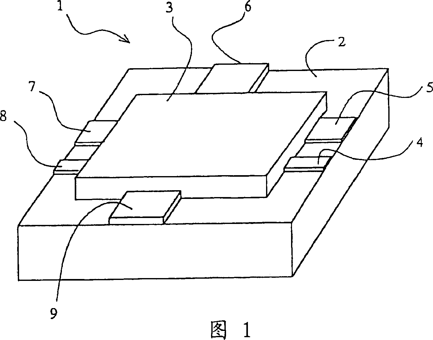
[0133] FIG. 1 is an external view illustrating the configuration of a unit element of an electromechanical switch according to a first embodiment.
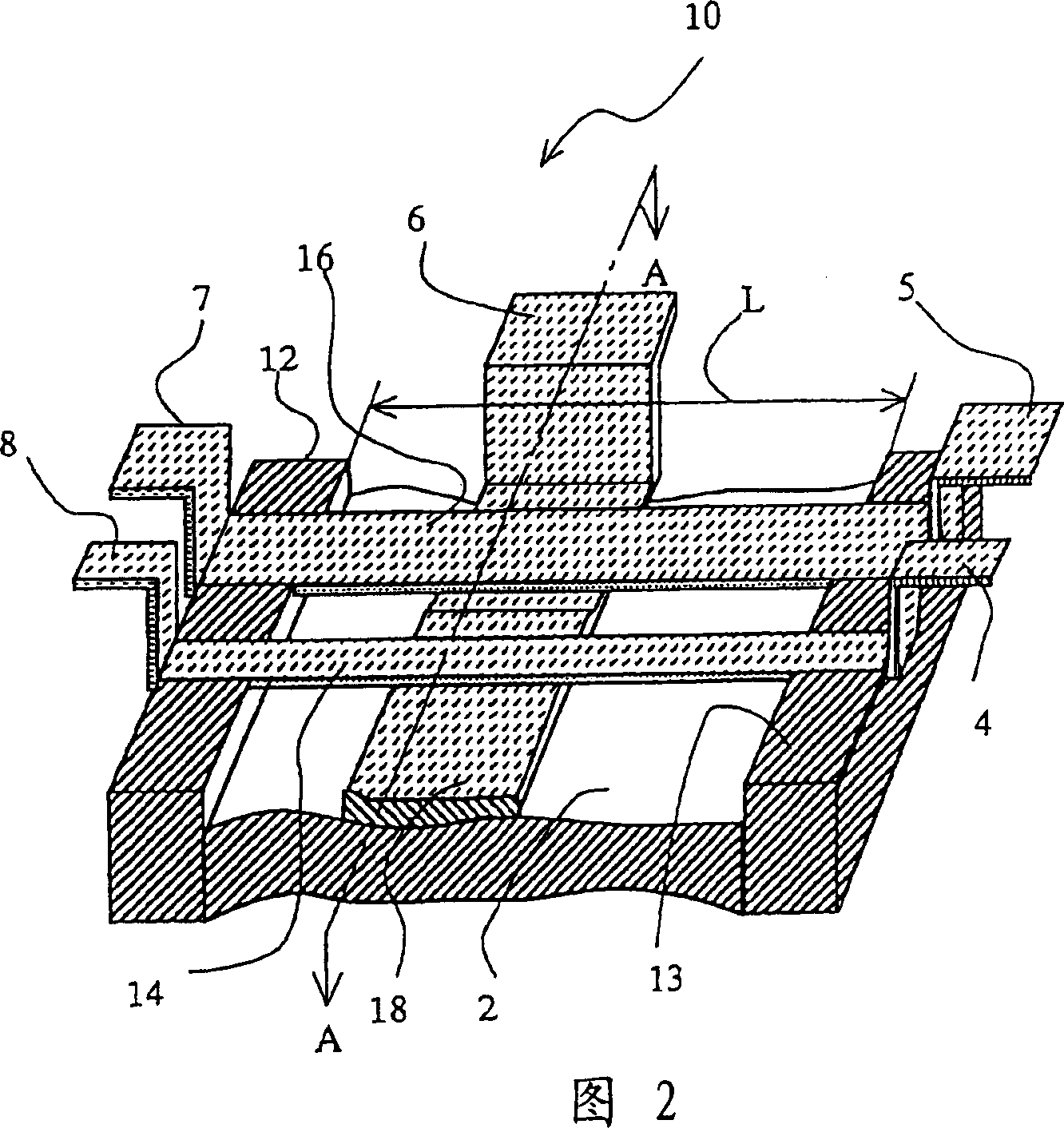
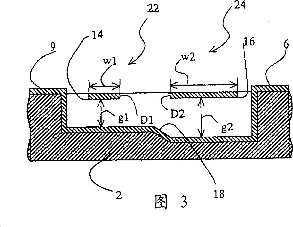
[0134] 2 is a partial cross-sectional view illustrating the configuration of an essential portion of each of the first electromechanical switch and the second electromechanical switch of the first embodiment.
[0135] As shown in FIGS. 1 and 2, an electromechanical switch 1 according to the first embodiment has an electromechanical switch main body 10 formed on a silicon substrate 2 and covered with a sealing cover glass 3, and also has an electromechanical switch functioning as an input / output terminal. A first electrode terminal 4 , a second electrode terminal 5 , a third electrode terminal 6 , a fourth electrode terminal 7 , a fifth electrode terminal 8 and a sixth electrode terminal 9 .
[0136] As shown in FIG. 2, the electromechanical switch body 10 has a first movable electrode 14 and a second movable electrode 16, both end...
no. 2 example
[0225] Next, a second embodiment will be described below.
[0226] Fig. 17 is a schematic diagram illustrating the configuration of an example of the second embodiment.
[0227] There are no restrictions on the construction and material of the electromechanical switch. As long as the response time of the electromechanical switch corresponding to the natural vibration of the movable electrode is obtained by setting the shape and material of the movable electrode, which is equal to or less than an expected value, the set shape and material can be used. In a second embodiment, a relative change in spring force is implemented.
[0228] As shown in FIG. 17, the electromechanical switch 200 according to the second embodiment has a first movable electrode 202, a second movable electrode 204, and a third movable electrode 206, and both ends of each movable electrode are placed and fixed to Formed on the first anchor 201 and the second anchor 203 on the silicon substrate 2 . The for...
no. 3 example
[0252] Next, a third embodiment of the present invention will be described below. Fig. 19 is a top view illustrating an electromechanical switch according to a third embodiment of the present invention. Similar to the first embodiment, the electromechanical switch according to the third embodiment includes a plurality of switches having different spring forces. The third embodiment prevents the disadvantage of not being able to pull in the second movable electrode with a strong spring force in the disconnected state, even if the first movable electrode is locked by the fixed electrode due to some malfunction; And the second movable electrode is finally in the middle position, so that both the first movable electrode and the second movable electrode are in the disconnected state, which is similar to the first embodiment.
[0253] That is, each of the first movable electrode and the second movable electrode will It will also reach the middle position through free vibration, so...
PUM
| Property | Measurement | Unit |
|---|---|---|
| Young's modulus | aaaaa | aaaaa |
| Density | aaaaa | aaaaa |
| Width | aaaaa | aaaaa |
Abstract
Description
Claims
Application Information
 - R&D
- Intellectual Property
- Life Sciences
- Materials
- Tech Scout
- Unparalleled Data Quality
- Higher Quality Content
- 60% Fewer Hallucinations
Browse by: Latest US Patents, China's latest patents, Technical Efficacy Thesaurus, Application Domain, Technology Topic, Popular Technical Reports.
© 2025 PatSnap. All rights reserved.Legal|Privacy policy|Modern Slavery Act Transparency Statement|Sitemap|About US| Contact US: help@patsnap.com