
Battery connecting wafer structure

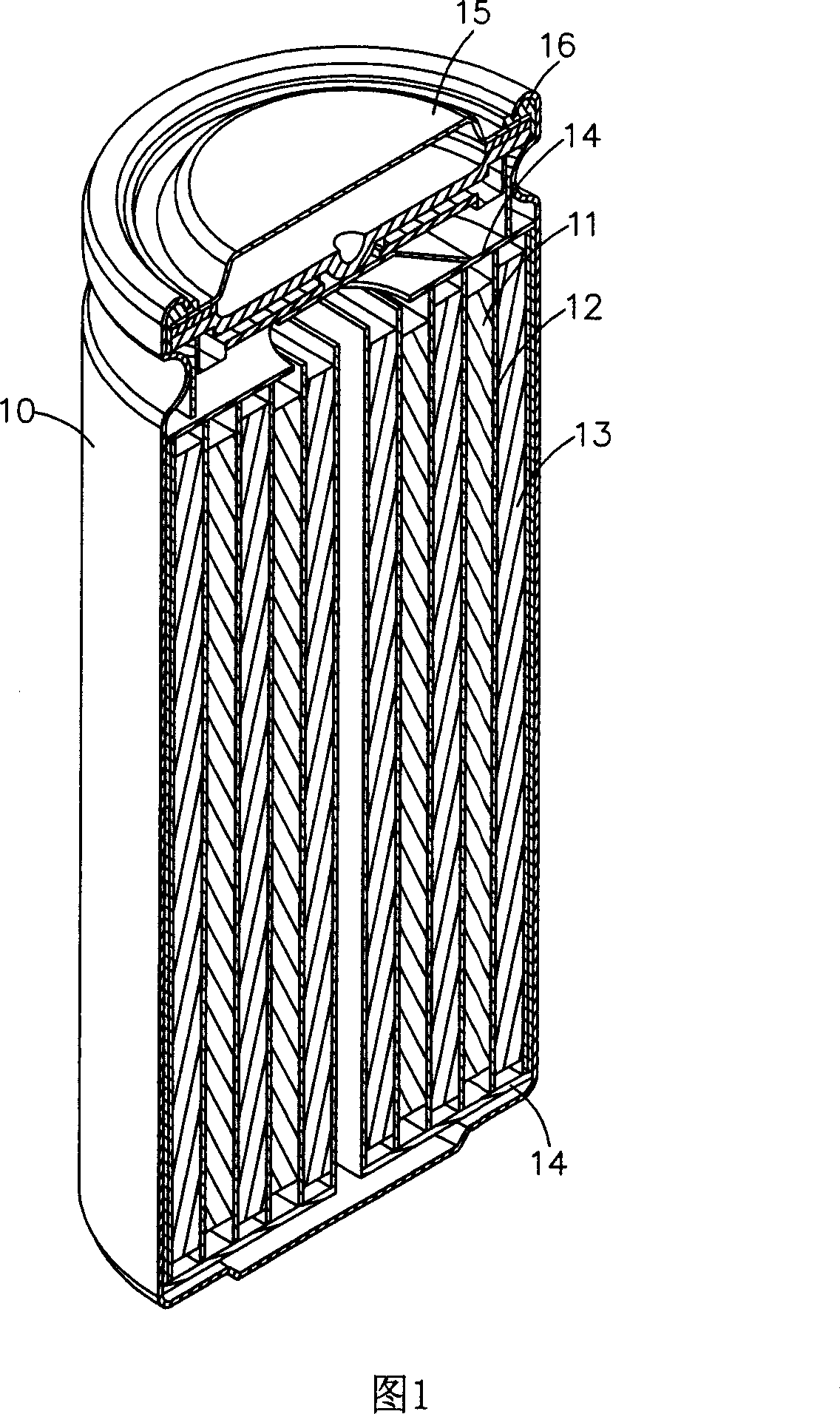
A battery connecting piece and battery technology, which is applied in the direction of conductive connection, electrical component connection, connection, etc., can solve the problems of liquid leakage, reduced adhesion, unstable configuration of the electrode cover 25, etc., to avoid displacement, protect adhesion, and buffer. Effects of inter-cell stress

Inactive Publication Date: 2007-04-04
伍贻杰
View PDF0 Cites 27 Cited by
  • Summary
  • Abstract
  • Description
  • Claims
  • Application Information

AI Technical Summary

Problems solved by technology

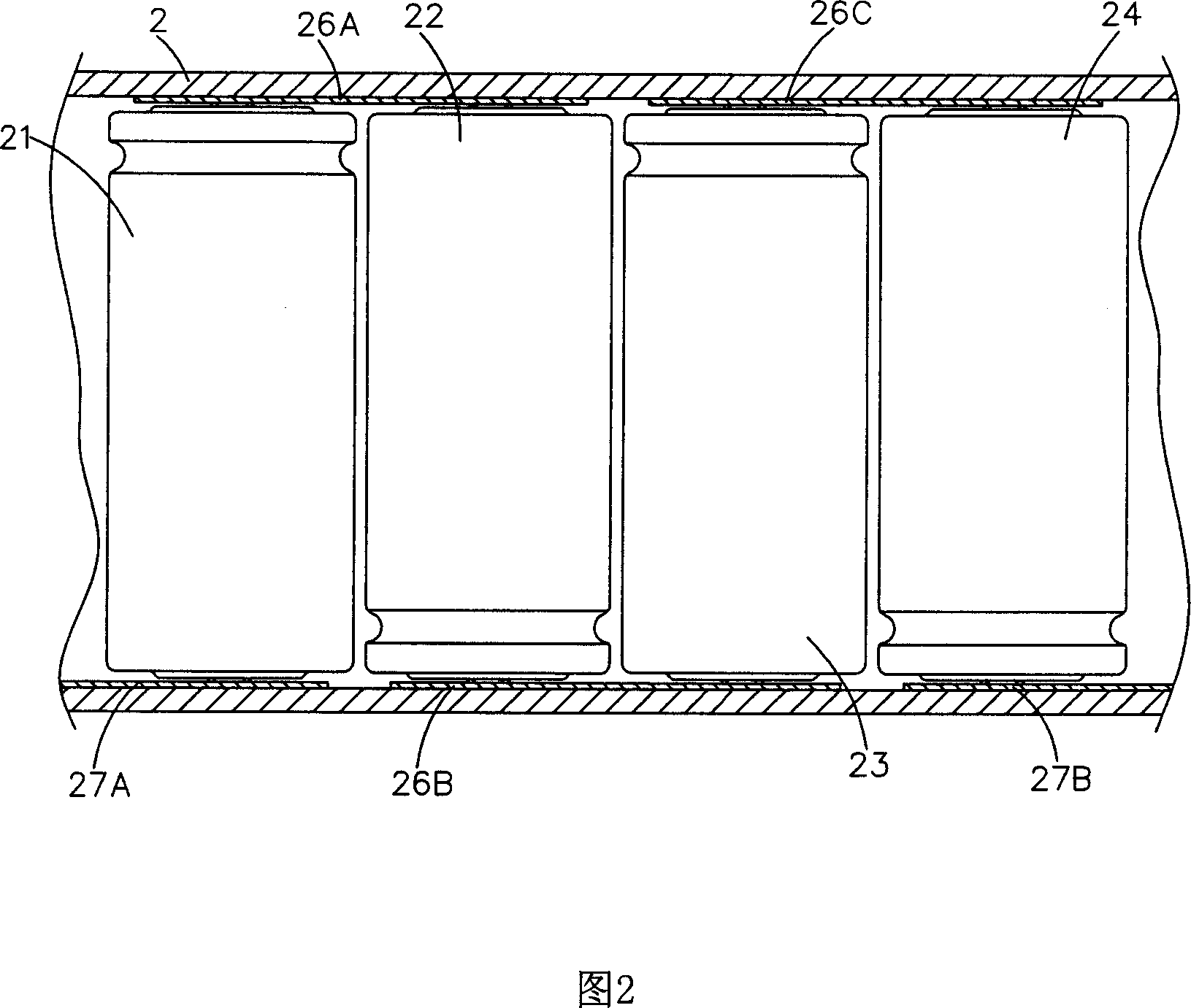
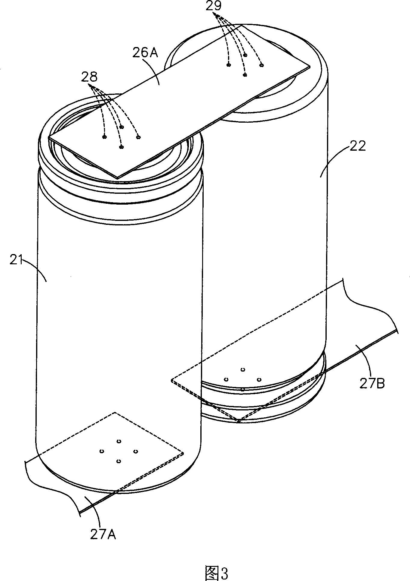
When the battery 21 is subjected to rightward stress and the battery 22 is not subject to any stress, the battery connecting piece 26A connected to the two batteries 21, 22 is an integrally formed metal sheet, which is not easy to deform or move, so it is welded on the battery connecting piece 26A The solder joints 28, 29 will not move in any way, because the electrode cover 25 is pressed on the casing by an intermediary, so that the configuration of the electrode cover 25 is unstable, and it is easy to move due to the stress on the battery or the battery connecting piece. , this kind of movement will cause the tightness between the shell and the shell to decrease, and then cause liquid leakage
[0008] In view of the above-mentioned shortcomings, in this technical field, there is an urgent need for a battery connection sheet structure, which can reduce the relative gap between batteries in rechargeable battery packs with spot-welded battery connection sheets without changing the manufacturing process of the battery body. Movement stress caused by poor fit

Method used


Image

  • Battery connecting wafer structure
  • Battery connecting wafer structure
  • Battery connecting wafer structure

Examples


Embodiment Construction

[0053] In order to clearly describe the structure and function of the present invention, the embodiments of the present invention will be described in detail below with reference to the drawings.

[0054]Please refer to FIG. 5 , which shows a battery connecting piece according to an embodiment of the present invention. The present invention provides an integrally formed battery connection sheet structure, which includes at least one bent portion 51 and connecting portions 52A, 52B connected to both sides of the bent portion 51, please refer to FIG. 6A, which is the battery connection in FIG. 5 The side view of the sheet fixed on the battery A, B, the battery connection sheet is fixed on the electrode cover 55 by the connection part 52A, 52B through the welding point 58, and in Fig. 6B, it shows that this embodiment can be used for both batteries at the same time end link.

[0055] Please refer to FIG. 7, which shows the variation of the embodiment of the present invention in ...


PUM


Abstract

The invention is concerned with the connecting slice structure of battery, which assorts with at least two batteries set of the battery cover, it is: the connecting slice structure of battery is integrative formation and with at least one bending part and the connecting part located at the both sides of the bending part, fixes the connecting slice structure of battery on the battery cover by the connecting part, and creates distortion of the bending part when the battery gets stress in order to avoid the battery cover to create movement. The invention can make the battery main body unchanged and protects the thickness of the battery.

Description

technical field [0001] The invention relates to a battery connecting piece structure, specifically a battery connecting piece structure used to protect the battery tightness, and belongs to the field of battery connecting pieces. Background technique [0002] With the advancement of science and technology, there are more and more personalized electronic products. In order to improve the practicability of these products, their designs tend to be carried around, and batteries have also become the main source of power supply. Today, with the rising awareness of environmental protection, they can be thrown away as soon as they are used. Rechargeable batteries have been gradually eliminated and replaced by reusable rechargeable batteries. Affected by the type of rechargeable batteries, it is often necessary to connect multiple rechargeable batteries in series to obtain sufficient voltage. These products integrate individual dedicated rechargeable batteries. [0003] Please refer...

Claims


Application Information

Patent Timeline
IPC IPC(8): H01M2/20H01R11/00H01M50/503H01M50/507H01M50/514
CPCY02E60/10
Inventor 伍贻杰
Owner 伍贻杰
Learn More