Optical-element washing structure

A technology of optical components and clamping structure, applied in optics, glasses/protective glasses, instruments, etc., can solve the problems of difficult cleaning in large quantities and low cleaning efficiency, and achieve the effect of meeting mass production requirements and improving cleaning efficiency.

Inactive Publication Date: 2007-03-28
HONG FU JIN PRECISION IND (SHENZHEN) CO LTD +1
View PDF1 Cites 4 Cited by
  • Summary
  • Abstract
  • Description
  • Claims
  • Application Information

AI Technical Summary

Problems solved by technology

However, the cleaning box 100 can only accommodate a single lens, and its cleaning efficiency is low, and it is not easy to perform a large amount of cleaning.

Method used


Image

  • Optical-element washing structure
  • Optical-element washing structure
  • Optical-element washing structure

Examples


Embodiment Construction

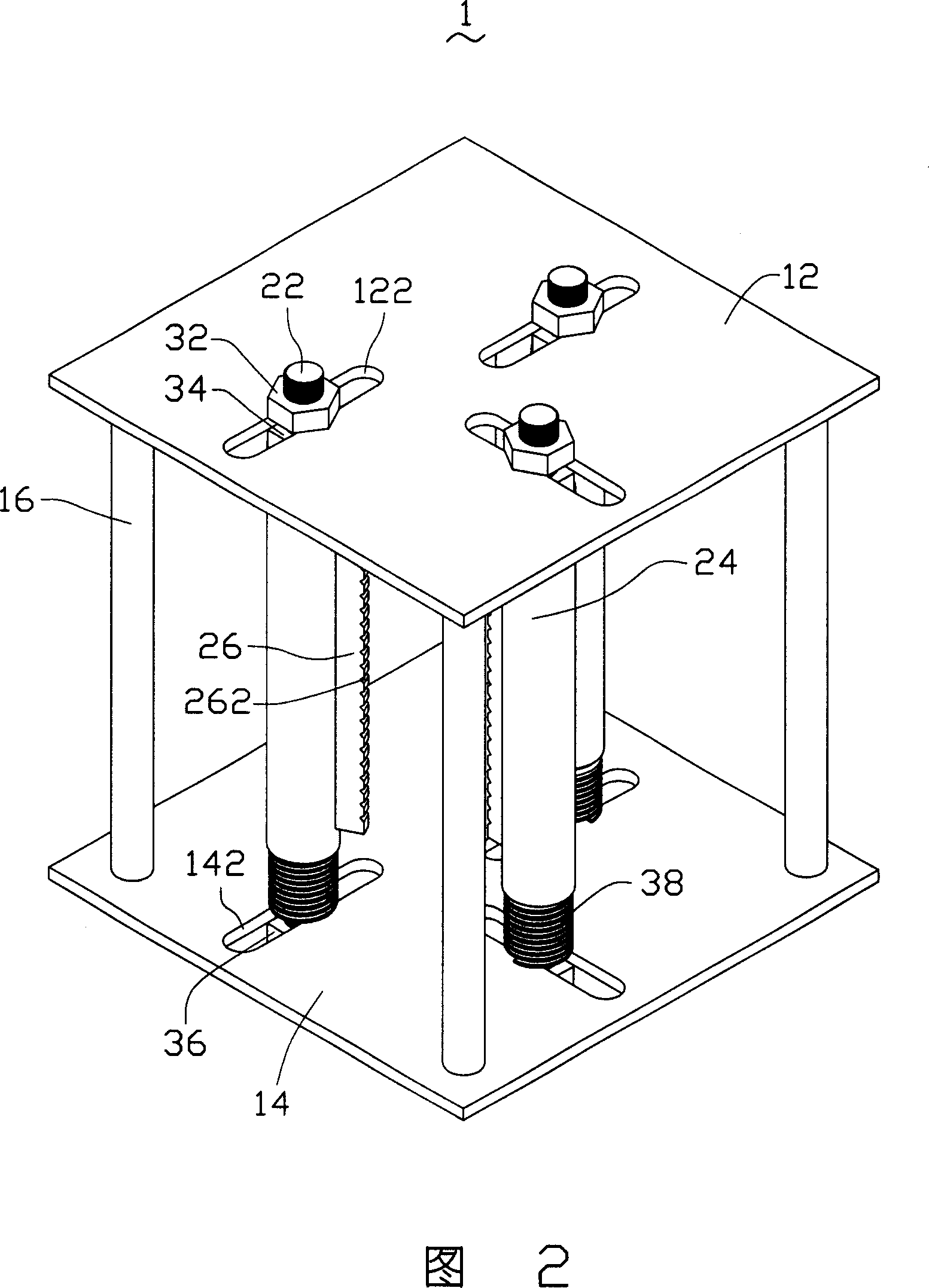
[0014] Please refer to FIG. 2 and FIG. 3 , the optical element cleaning structure 1 according to the first embodiment of the present invention includes a frame (not shown), three supporting devices 20 and three height adjusting devices (not shown).

[0015] The frame includes a square first holding plate 12 , a square second holding plate 14 and a plurality of supporting columns 16 . In this embodiment, a plurality of supporting columns 16 are used to support and connect the first holding plate 12 and the second holding plate 14 . Three elongated through holes 122 are opened on the first holding plate 12 , and the three elongated through holes 122 are arranged in a T shape. Corresponding to the three elongated through holes 122 of the first elongated plate 12 , three elongated through holes 142 are defined on the second holding plate 14 , and the three elongated through holes 142 are also arranged in a T shape.

[0016] The carrying device 20 includes a carrying rod 22 , a sle...


PUM


Abstract

The invention provides a cleaning structure for the optical element which includes a fixed board, at least one high adjustment device, some load-bearing poles set on the fixed board, some clamping structures set on the load-bearing poles and at least one sleeve. At least one strip pylome which is passed by at least one load-bearing pole is set on the fixed board; the high adjustment device includes an adjusting nut and an elastic element; the sleeve is covered on at least one load-bearing pole which the two ends are covered with the elastic element and the adjusting nut. The cleaning structure can revise the position of the clamping structure easily compared to the present technology, so it can clamp many optical elements at one time to improve the efficient, also it can clean the optical element with different size.

Description

【Technical field】 [0001] The invention relates to an optical element cleaning structure, in particular to an optical element cleaning structure for cleaning lenses. 【Background technique】 [0002] At present, the application of optical products such as mobile phones and digital cameras is becoming more and more popular, so there are more and more types of optical components (such as lenses) and they are getting smaller and smaller. Cleaning optical components is the first step in the optical coating process. The quality of optical components, the cleaning of optical components has become an important issue. [0003] Generally, the cleaning of optical components only needs to put the workpiece into a container, clean it with ultrasonic vibration, and then dry it. No. 99234336.4 utility model patent disclosed in China on April 26, 2000 discloses a kind of ultrasonic cleaning machine, please refer to Fig. 1, this cleaning machine is made up of cleaning box 100, casing 200 and ...

Claims


Application Information

Patent Timeline
Patent Type & Authority Applications(China)
IPC IPC(8): G02C13/00
Inventor 颜士杰
Owner HONG FU JIN PRECISION IND (SHENZHEN) CO LTD
Why Eureka
Try Eureka