
Heat exchanger bracket and air conditioner within the same

A technology of heat exchangers and air conditioners, which is applied in the direction of household heating, household heating, heating methods, etc., can solve the problem that condensed water cannot flow smoothly to or outside the drainage tank, and the drainage tank is biased to the inside of the drainage tank side or outside

Inactive Publication Date: 2007-03-28
SAMSUNG ELECTRONICS CO LTD
View PDF0 Cites 2 Cited by
  • Summary
  • Abstract
  • Description
  • Claims
  • Application Information

AI Technical Summary

Problems solved by technology

[0009] However, the existing air conditioner as mentioned above is set because the lower end of the heat exchanger is simply placed on the drain tank, so the lower end of the heat exchanger cannot be located in the center of the drain tank and is biased towards the inside or outside of the drain tank.
Therefore, there is a problem that the condensed water flowing down from the inner surface and the outer surface of the heat exchanger cannot smoothly flow into the inside of the drain tank but flows out of the drain tank.

Method used


Image

  • Heat exchanger bracket and air conditioner within the same
  • Heat exchanger bracket and air conditioner within the same
  • Heat exchanger bracket and air conditioner within the same

Examples


Embodiment Construction

[0026] Hereinafter, the heat exchanger bracket and the air conditioner provided with the heat exchanger bracket according to the preferred embodiments of the present invention will be described in detail with reference to the accompanying drawings.

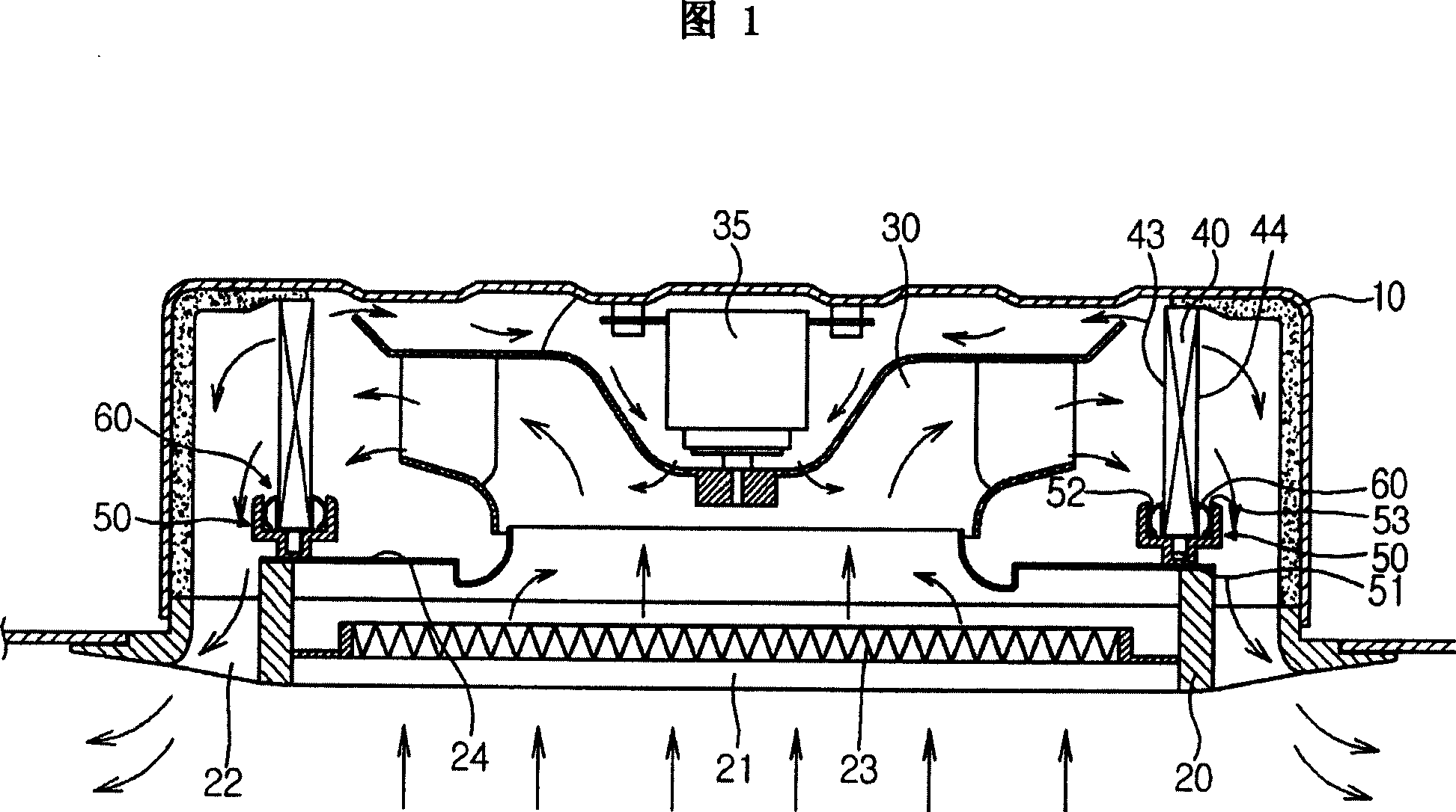
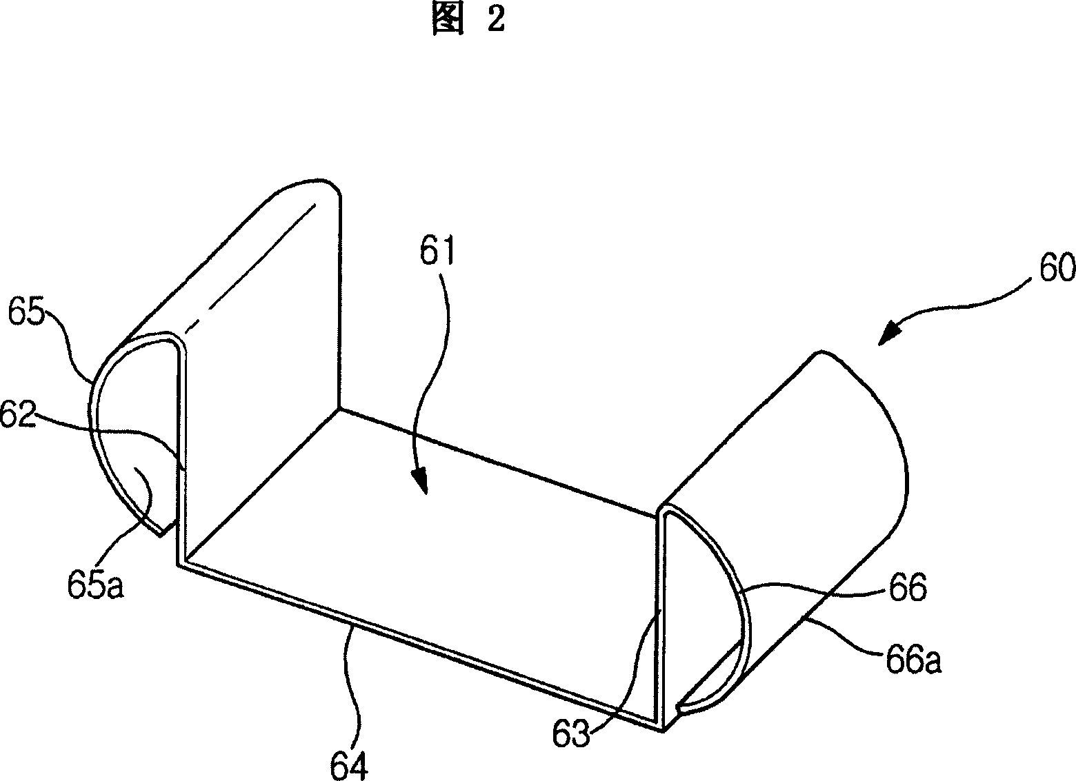
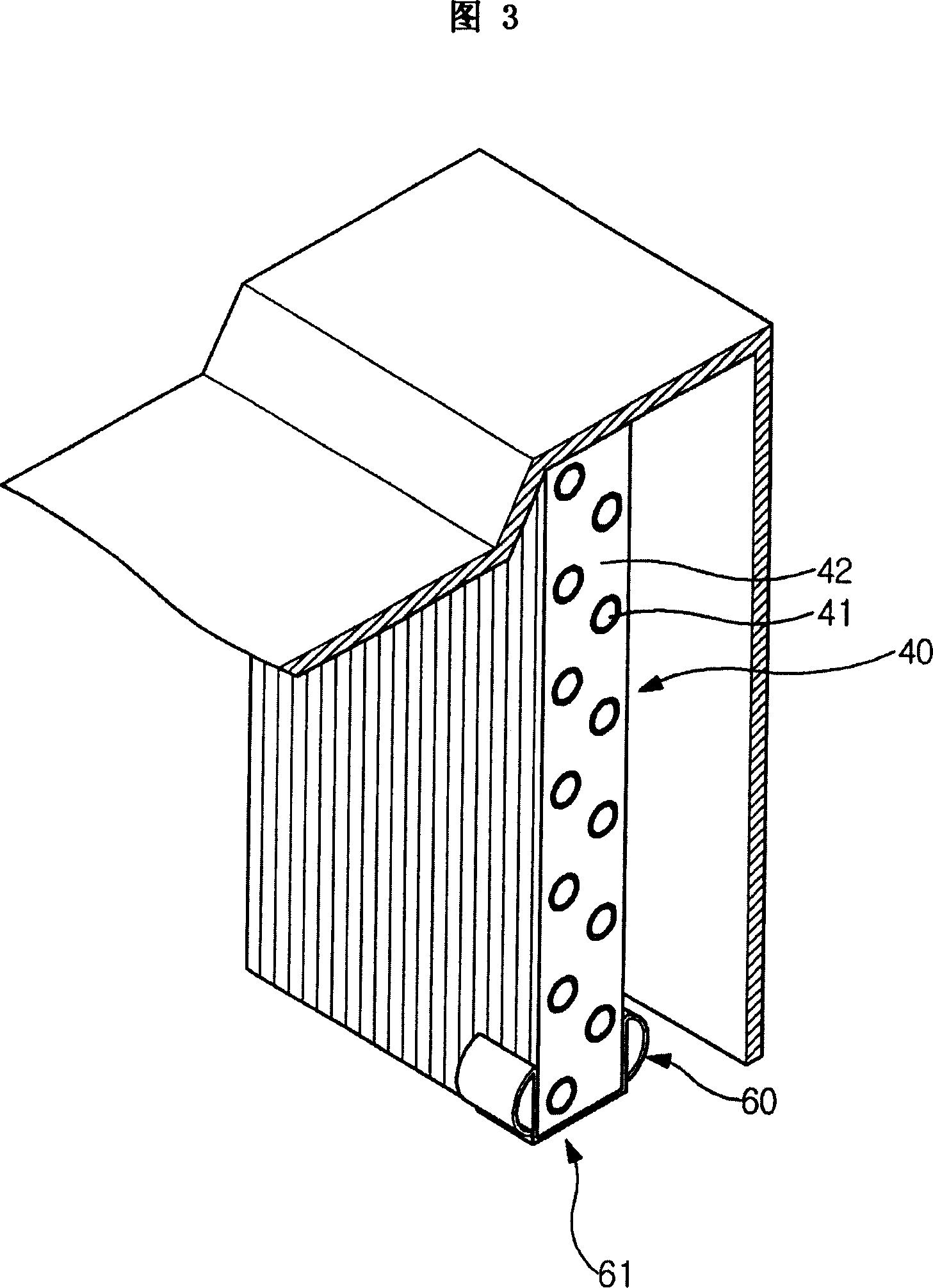
[0027] Fig. 1 is a side sectional view roughly showing the structure of an air conditioner provided according to a preferred embodiment of the present invention; Fig. 2 is a schematic diagram roughly showing a structure of a heat exchanger support provided according to a preferred embodiment of the present invention; Fig. 3 is a schematic diagram showing a structure according to the present invention A schematic diagram of the state in which the heat exchanger bracket provided by the preferred embodiment of the invention is combined with the heat exchanger. Figure 4 is a schematic diagram showing the state in which the heat exchanger combined with the heat exchanger bracket provided by the preferred embodiment of the invention is pl...


PUM


Abstract

The present invention provides a air-conditioner which comprises a heat exchanger 40, a ventilation fan 30 used to eject air to the exchanger 40, a waterspout 50 used to accommodate lower part of a heat exchanger 40, a combination 61 integrating to the lower part of a heat exchanger 40, a heat exchanger bracket 60 comprising two isolating parts 65 and 66 respectively mounted on two sidewalls 62 and 63 of a combination 61. The isolating parts 65 and 66 respectively contact two inner sidewalls 52 and 53 of a waterspout 50 and then separate a combination 61 from the two inner sidewalls 52 and 53 of a waterspout 50. According to the present invention, condensed water produced outside a heat exchanger 40 is prevented from flowing into exterior of the waterspout 50 and flows into interior of a waterspout 50 easily, since the heat exchanger bracket 60 is mount between the heat exchanger 40 and the waterspout 50, wherein the heat exchanger 40 locates at the center of the waterspout 50.

Description

technical field [0001] The invention relates to an air conditioner, in particular to a heat exchanger support for supporting a heat exchanger so that it is located in the center of a drainage tank and an air conditioner with the heat exchanger support. Background technique [0002] Generally, an air conditioner is a device for conditioning indoor air using a refrigeration cycle, and is composed of an outdoor unit installed outdoors and an indoor unit installed indoors. The outdoor unit consists of a compressor for compressing refrigerant, a condenser for condensing the compressed refrigerant, and an exhaust fan for forcedly exhausting air to the condenser. In addition, the indoor unit includes an evaporator for exchanging heat between the refrigerant and the indoor air, and an exhaust device for forcibly exhausting the indoor air for smooth heat exchange between the evaporator and the air. [0003] In the air conditioner described above, the indoor unit has a wall-mounted t...

Claims


Application Information

Patent Timeline
Patent Type & Authority Applications(China)
IPC IPC(8): F24F13/30
CPCF24F13/22F24F13/30
Inventor 朱元一
Owner SAMSUNG ELECTRONICS CO LTD
Learn More