
Sphygmus dynamic image information collecting system

A dynamic image and information collection technology, applied in medical science, sensors, inoculation and ovulation diagnosis, etc., can solve problems such as the difficulty of skin deformation with a linear relationship, the limitation of the number of detection points, and the application of pulse information that restricts the objectification of TCM pulse diagnosis.

Inactive Publication Date: 2007-03-14
LANZHOU UNIVERSITY OF TECHNOLOGY
View PDF0 Cites 19 Cited by
  • Summary
  • Abstract
  • Description
  • Claims
  • Application Information

AI Technical Summary

Problems solved by technology

These improved detection methods are greatly limited by the number of detection points due to the influence of factors such as the sensor structure volume, the performance of sensitive components, and the manufacturing process.
At present, there are only research reports on five-way sensors and 9-point PVDF pulsometers, and it is difficult to have a linear relationship between the output of the sensor and the skin deformation caused by the pulse when cutting the pulse.
Obviously, the pulse map collected by the above-mentioned detection system is difficult to quantitatively and accurately reflect all the constituent elements of the pulse condition, which restricts the research on the objectivity of TCM pulse diagnosis and the application of pulse information.

Method used


Image

  • Sphygmus dynamic image information collecting system
  • Sphygmus dynamic image information collecting system
  • Sphygmus dynamic image information collecting system

Examples


Embodiment Construction

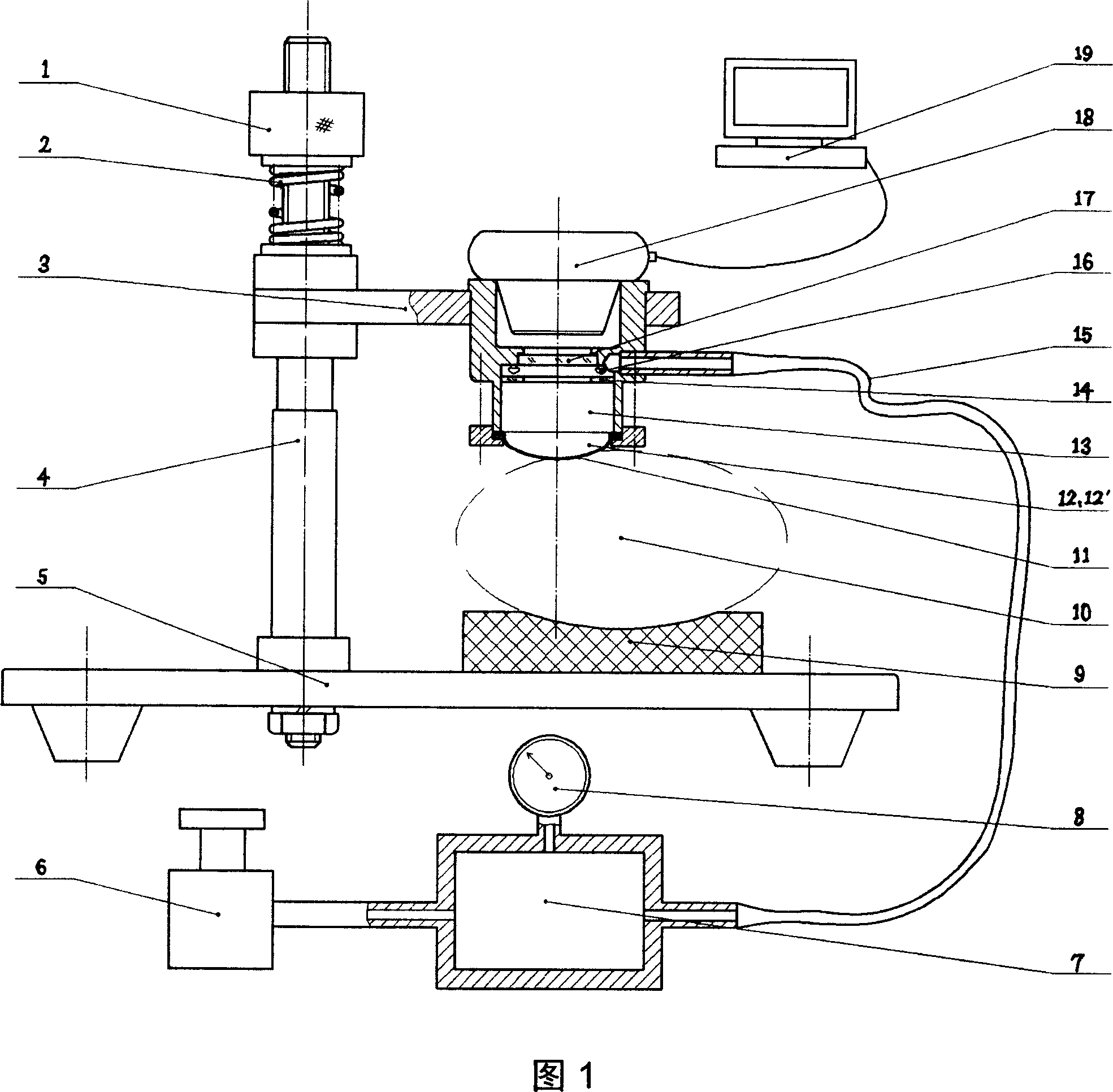
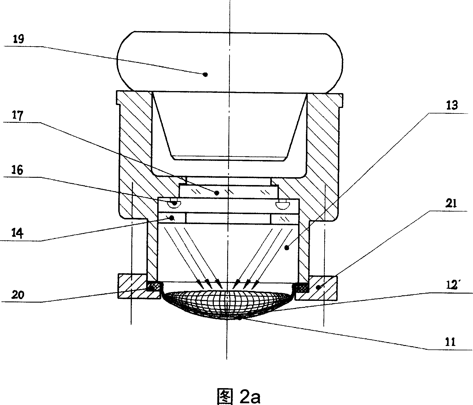
[0007] As shown in Figure 1, it is a structural diagram of the pulse dynamic image information acquisition system of the present invention. The pressure-sealed cavity 13 is installed on the horizontal bracket 3, the horizontal bracket 3 is installed on the vertical column 4, and the flexible detection contact 12 is installed on the At the lower end of the pressure sealing chamber 13, the air pump 6 is connected to the air pressure buffer chamber 7, and the air pressure buffer chamber 7 is connected to the pressure sealing chamber 13 through the air path 15. The film 12' is attached to the inside of the flexible detection contact 12, and the film 12' is textured The illumination light source 16 is installed in the pressure sealed cavity 13 at a position above the flexible detection contact 12, the image collector 18 is installed on the upper end of the pressure sealed cavity 13, and the image collector 18 is connected to the computer 19 through a signal line. A ground glass sheet 1...


PUM


Abstract

A pulse dynamic image acquisition system involves herbalist medicine diagnosis device, especially the pulse information collection devices. The sealed pressure cavity is fixed on the level bracket, and the level bracket is fixed on the vertical columns. Flexible contact is fixed on the top of the sealed pressure cavity, the air pump is linked with the air pressure buffer cavity and the air pressure buffer cavity is linked with the sealed pressure cavity by the air circuit. The membrane with veins is affixed to the lining of the flexible contact, the lighting is fixed in the sealed pressure cavity the where above the flexible contact. The image acquisition device is installed on the upside of sealed pressure cavity, and the image acquisition devices connected with the computer through the signal line. A piece of ground glass is fixed between the lighting and the flexible contact. The invention can detect the image of the skin surface of the position where it feels the pulse when pulse throbs, and then gets multi-dimensional, comprehensive and dynamic image information of pulse.

Description

Technical field [0001] The invention relates to a traditional Chinese medicine diagnostic device, in particular to a pulse information collection device. technical background [0002] The sensors currently used for pulse information collection mainly include: liquid, photoelectric, strain, and PVDF sensors. The liquid sensor is a pressure-sensitive surface made of a film that deforms after being pressed, causing the conductive liquid column inside the container to rise and fall, and the resistance value changes, thereby converting the pulse pressure signal into an electrical signal. The photoelectric sensor is forced by a thin rod and moves upward to change the amount of light transmitted. The electrical signal output by the photocell reflects the force. Strain gauge pressure sensor is a kind of sensor that is widely used in pulse meter. It deforms after being stressed by the strain gauge, which causes the resistance value to change, and the change in the output voltage of the br...

Claims


Application Information

Patent Timeline
Patent Type & Authority Applications(China)
IPC IPC(8): A61B5/0245A61B10/00
Inventor 张爱华朱亮
Owner LANZHOU UNIVERSITY OF TECHNOLOGY
Learn More