Optical module and making method thereof

A technology for a backlight module and a manufacturing method, applied in optics, nonlinear optics, instruments, etc., can solve problems such as easy loosening, and achieve the effect of improving rigidity and enhancing rigidity

Inactive Publication Date: 2007-03-07
INNOCOM TECH SHENZHEN +1
View PDF0 Cites 1 Cited by
  • Summary
  • Abstract
  • Description
  • Claims
  • Application Information

AI Technical Summary

Problems solved by technology

[0005] The metal back plate 11 of the backlight module 1 is combined with the plastic frame 12 in the way that the clamping block 122 is engaged with the fixing hole 112, which is prone to loosening.

Method used


Image

  • Optical module and making method thereof
  • Optical module and making method thereof
  • Optical module and making method thereof

Examples


Embodiment Construction

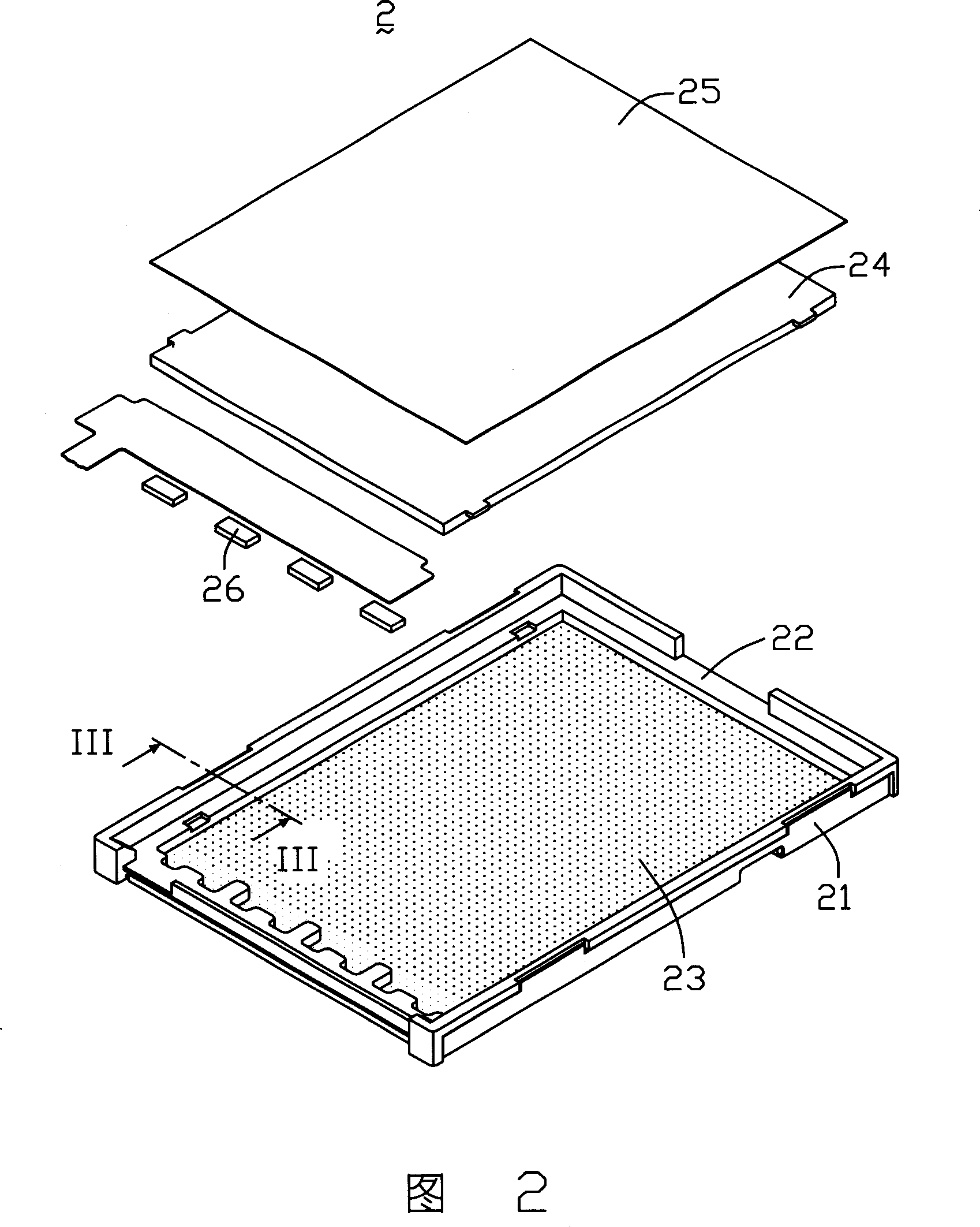
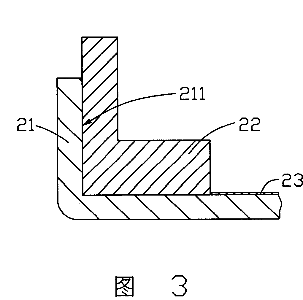
[0015] The backlight module of the present invention is shown in FIG. 2 and FIG. 3 , FIG. 2 is an exploded view of the backlight module 2 , and FIG. 3 is a sectional view along III-III of the backlight module 2 shown in FIG. 2 . The backlight module 2 includes a metal back plate 21 having an inner bottom surface (not shown) and an inner wall 211, a plastic frame 22, a reflective layer 23 plated on the inner bottom surface of the metal back plate 21, a light guide plate 24, and a diffuser located above the light guide plate 24. plate 25 and a light source 26 adjacent to one end of the light guide plate 24 . The plastic frame 22 is integrally formed with the metal backboard 21 , and the plastic frame 22 covers the inner wall of the metal backboard 21 . The light guide plate 24 is located above the metal back plate 21 . The metal backplane 21 can be an aluminum backplane. The plastic frame is made of polycarbonate material. The reflective layer can be made of metal with high r...


PUM


Abstract

This invention relates to one aphototropism module, which comprises baseboard, glue frame, and optical elements, wherein the glue frame and baseboard is in one shape to contain one space with optical elements in. The aphototropism module process method comprises the following steps: providing baseboard; providing glue frame materials and module modes and combining them within mode to form one containing space; providing optical elements to be put to the space.

Description

【Technical field】 [0001] The invention relates to a backlight module and a manufacturing method thereof. 【Background technique】 [0002] Due to the advantages of lightness, thinness, and low power consumption, liquid crystal display devices are widely used in modern information equipment such as notebook computers, mobile phones, and personal digital assistants. Since the liquid crystal itself does not have light-emitting properties, it is necessary to provide a backlight module for it to realize the display function. [0003] Please refer to FIG. 1 , a backlight module 1 of the prior art includes: a metal back plate 11 having a side 111 and an inner bottom surface 113 , a plastic frame 12 including a side wall 121 , a reflector 13 located above the inner bottom surface 113 , The light guide plate 14 above the reflection plate 13 , the diffuser plate 15 above the light guide plate 14 , and the light source 16 adjacent to one end of the light guide plate 14 . The metal back...

Claims


Application Information

Patent Timeline
Patent Type & Authority Applications(China)
IPC IPC(8): G02F1/1335
Inventor 黄星童陈英杰
Owner INNOCOM TECH SHENZHEN
Why Eureka
Try Eureka