
Electromagnetic switch device in particular a contactor

A technology of electromagnetic switches and contactors, applied in the direction of electric switches, electromagnetic relays, detailed information of electromagnetic relays, etc., can solve problems such as difficult to reach the coil connection terminals, no way to reach the coil connection terminals, complex structure, etc.

Inactive Publication Date: 2007-02-21
SIEMENS AG
View PDF0 Cites 0 Cited by
  • Summary
  • Abstract
  • Description
  • Claims
  • Application Information

AI Technical Summary

Problems solved by technology

In this kind of electrical switch, due to its more complex structure, after the main line is connected, the coil connection terminal becomes difficult to reach
In the case of the additional installation of auxiliary electrical switches such as power switches and / or overload relays, the coil connection terminals are simply not accessible

Method used


Image

  • Electromagnetic switch device in particular a contactor
  • Electromagnetic switch device in particular a contactor
  • Electromagnetic switch device in particular a contactor

Examples


Embodiment Construction

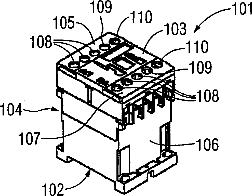
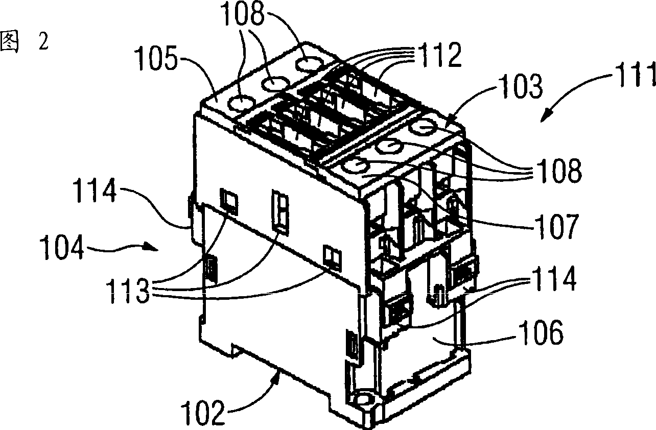
[0028] figure 1 A conventional contactor 101 based on the prior art is shown, with a rear face 102 facing downwards and a front face 103 facing upwards. On the front end face 103 of the contactor 101 , a row of upper connecting terminals 105 is arranged in the direction of the upper end face 104 of the contactor; a row of lower connecting terminals 107 is arranged in the direction of the lower end face 106 of the contactor. The two rows of connection terminals 105 and 107 each include three main current connection terminals 108 , one auxiliary switch connection terminal 109 and one coil connection terminal 110 . The upper row of connecting terminals 105 and the lower row of connecting terminals 107 are in the same plane. The main current connection terminals, auxiliary switch connection terminals and coil connection terminals 108, 109 and 110 are all made as screw connection terminals. The upper row of connection terminals 105 is used as an input terminal, and the lower row ...


PUM


Abstract

The invention relates to an electromagnetic switch device, in particular a contactor. According to the invention, the manipulation of coil connectors for an electromagnetic switch device may be improved with the use of a coil connector clamping block with at least one coil connector clamp , whereby the at least one coil connector clamp lies on a plane with an auxiliary switch connection.

Description

technical field [0001] The invention relates to an electromagnetic switch, especially a contactor. Background technique [0002] In order to control the contactor, a voltage must be applied to the drive of the contactor. It is known in this respect to provide at least two coil connection terminals fixedly mounted on the contactor housing. Because contactors may be connected in various ways to other electrical switches, these coil connection terminals are often covered so that on some contactors additional coil connection terminals are provided elsewhere in the contactor housing. In particular, if the coil connection terminals are arranged next to the connection terminals for the main current line or the auxiliary current line in order to be able to reach them from the front, then in combination with other electrical switches there will be at least A coil connection terminal is difficult to reach. In addition to those electrical switches whose coil connection terminals are...

Claims


Application Information

Patent Timeline
IPC IPC(8): H01H89/06H01H50/44
CPCH01H50/443H01H2011/0037H01H89/06
Inventor 约翰·德雷克斯勒彼得·哈廷格
Owner SIEMENS AG
Learn More