
Power unit start device for vehicle

A technology of starting device and power head, which is applied in the direction of starting device with manual crank, engine starting, motorcycle, etc., which can solve problems such as the limitation of operating range, and achieve the goal of ensuring operating space, improving starting performance, and improving operability Effect

Inactive Publication Date: 2010-06-16
HONDA MOTOR CO LTD
View PDF5 Cites 0 Cited by
  • Summary
  • Abstract
  • Description
  • Claims
  • Application Information

AI Technical Summary

Problems solved by technology

[0004] However, when the starting device is arranged on the driving wheel side, that is, on the rear wheel side, it must be moved to the rear position of the vehicle when starting.
Especially in the case of automatic tricycles, since the rear wheels are located on the left and right sides of the power head, the operating range (operating space) of the starting device will be limited by the rear wheels, which is also a problem

Method used


Image

  • Power unit start device for vehicle
  • Power unit start device for vehicle
  • Power unit start device for vehicle

Examples


Embodiment Construction

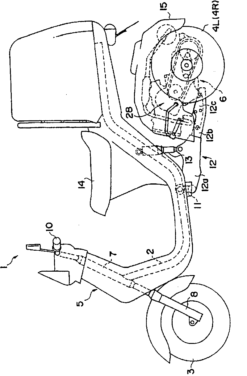
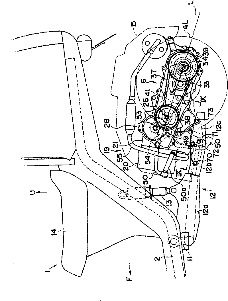
[0034] Hereinafter, best embodiments of the present invention will be described with reference to the drawings. First, use figure 1 A three-wheeled vehicle 1 equipped with a vehicle power head (hereinafter referred to as a power head) of the present invention will be described. An automatic tricycle 1 has a front wheel 3 and two rear wheels 4L, 4R. Viewed from the side, it has a U-shaped vehicle frame 2. The front end of the vehicle frame 2 supports the front wheel 3 through a steering mechanism 5. The vehicle frame 2 The rear portion is provided with the power head 6 that drives left and right rear wheels 4L, 4R. In addition, a vehicle seat 14 is installed on the top of the vehicle frame 2 rear end, and the power head 6 is covered with an engine cover 15 .

[0035] The steering mechanism 5 is attached to the front portion of the vehicle frame 2 and has a head pipe 7 extending up and down, and a rotatable steering shaft not shown in the drawing is attached to the head pipe 7...


PUM


Abstract

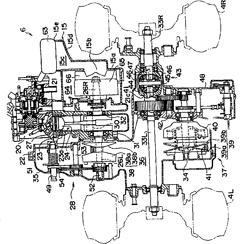
Provided a starting device for a vehicular power unit arranged on the opposite side of a drive wheel shaft sandwiching a crankshaft for outputting rotational driving force to a transmission device. The power unit 6 has an engine 19 loaded on a three-wheeled motorcycle 1 for outputting rotational driving force from the crankshaft 26 arranged in parallel to a rear wheel shaft 33 with rear wheels 4L,4R connected thereto, and a transmission 37 for transmitting the rotational driving force of the crankshaft 26 via a counter shaft arranged in parallel to the rear wheel shaft 33. The power unit 6 isstructured by a kick shaft 49 arranged in parallel to the crankshaft 26, a kick arm 50 arranged at the tip end of the kick shaft 49, and a kick starting mechanism 28 for starting the engine 19 by rotating the kick shaft 49 by making the kick arm 50 kick and transmitting the rotation to the crankshaft 26. The kick shaft 49 sandwiches the crankshaft 26 and is arranged on the opposite side of the rear wheel shaft 33.

Description

technical field [0001] The present invention relates to a vehicle power unit starting device mounted on a small vehicle such as an auto tricycle. The vehicle power unit includes an internal combustion engine and a speed change device. Background technique [0002] Conventionally, in small vehicles such as motorcycles and tricycles, a starter device for starting an engine is arranged in the drive wheel direction with respect to the crankshaft (for example, refer to Patent Document 1). [0003] Patent Document 1: Japanese Patent Laid-Open No. 2000-205091 [0004] However, when the starter device is arranged on the drive wheel side, that is, on the rear wheel side, it must be moved to a rear position of the vehicle when starting. Especially in the case of an automatic tricycle, since the position of the rear wheels is on the left and right sides of the power head, the operating range (operating space) of the starting device will be limited by the rear wheels, which is also a p...

Claims


Application Information

Patent Timeline
Patent Type & Authority Patents(China)
IPC IPC(8): F02N3/04B62M7/08B62K5/02B62K5/04B62M7/02
Inventor 锅谷真
Owner HONDA MOTOR CO LTD
Learn More