Lift dragging and driving mechanism

A technology of transmission mechanism and traction mechanism, which is applied to elevators, transportation and packaging in buildings, etc., can solve the problems of large space occupied by elevators and increase the cost of elevator construction, and achieve the effect of saving installation and use costs and preventing shaking.

Inactive Publication Date: 2007-01-03
CANNY ELEVATOR
View PDF0 Cites 1 Cited by
  • Summary
  • Abstract
  • Description
  • Claims
  • Application Information

AI Technical Summary

Problems solved by technology

However, the existing traction rope is usually a single strand, so the car running guide rail needs to be provided outside the car to prevent the car from shaking when it is running. The vertical accuracy needs to be very high to ensure that the car runs in the vertical direction. At the same time, the side of the counterweight also needs to be provided with a counterweight running guide rail to keep the counterweight running smoothly. The car running guide rail and the counterweight The setting of the heavy running guide rail not only increases the cost of the elevator, but also leads to a large occupied space in the entire elevator room

Method used


Image

  • Lift dragging and driving mechanism
  • Lift dragging and driving mechanism
  • Lift dragging and driving mechanism

Examples


Embodiment Construction

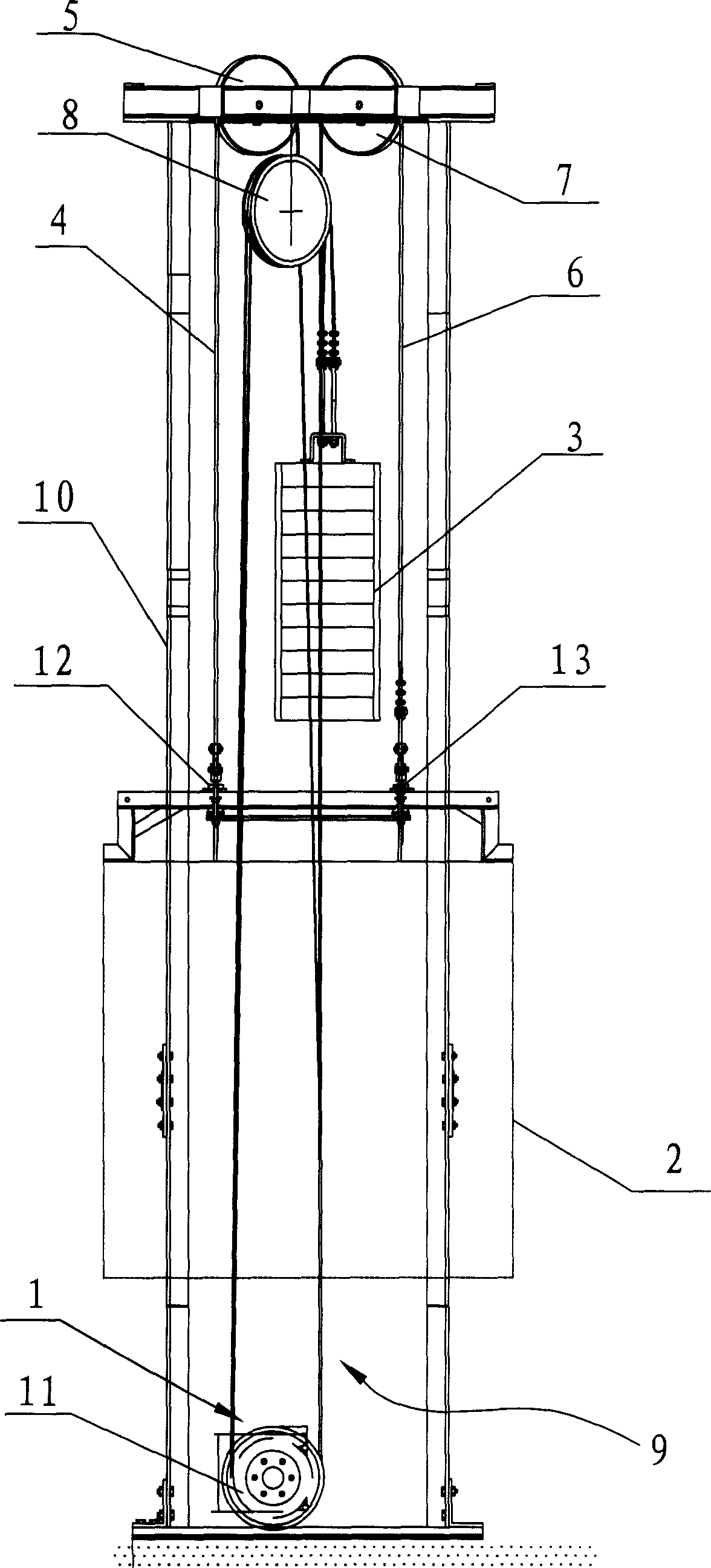
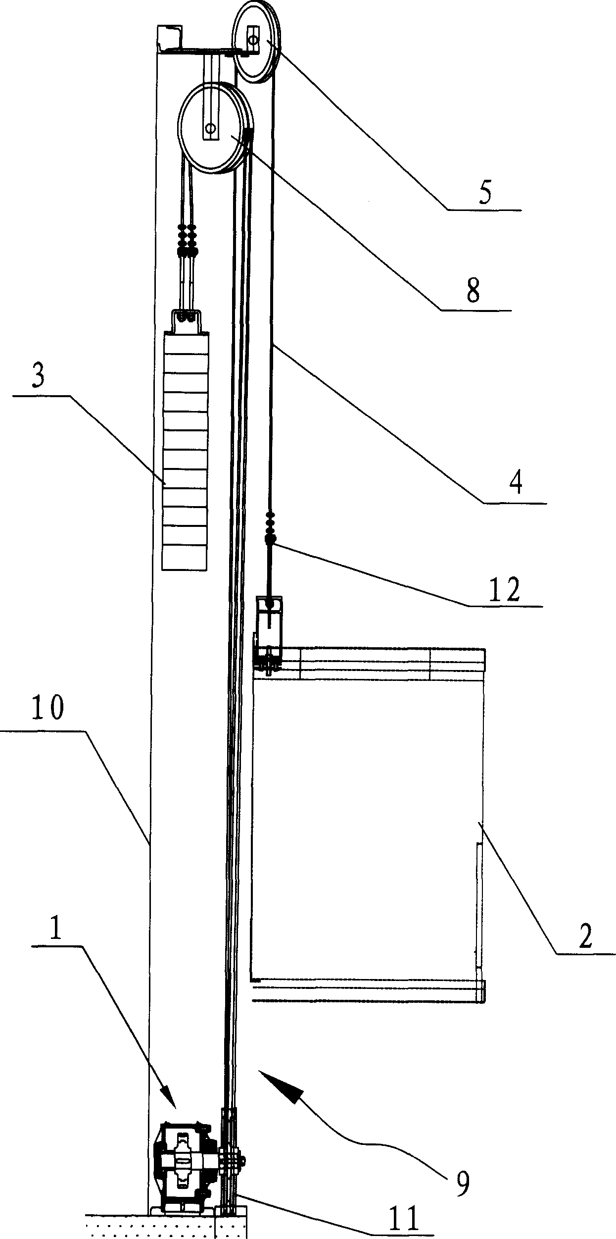
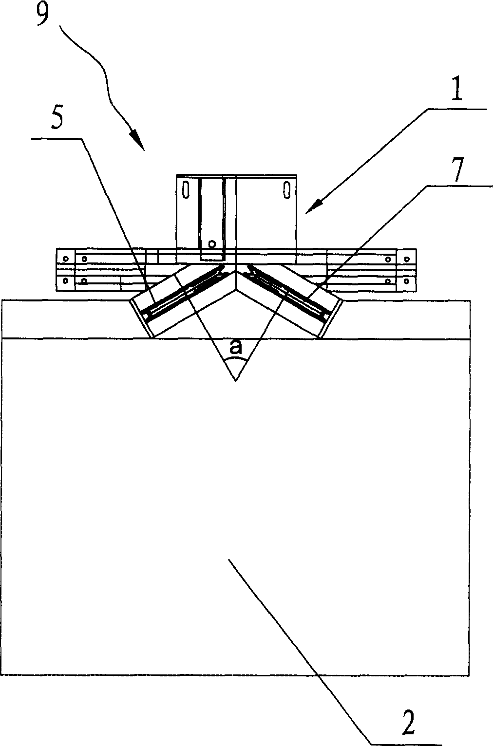
[0015] See attached figure 1 - attached image 3 As shown, a traction transmission mechanism of an elevator includes a traction motor 1, a car 2 that is drive-connected with the traction motor 1 through a traction mechanism 9, and the rotor of the traction motor 1 is connected in transmission There is an output turntable 11, the traction mechanism 9 includes a first traction rope 4 and a second traction rope 6 wound on the output turntable 11, and a fixed pulley for the first traction rope 4 to go around The first pulley 5, the second pulley 7 used as a fixed pulley for the second traction rope 6 to go around. Both sides of the top end of the car 2 are respectively symmetrically provided with a first connecting bracket 12 and a second connecting bracket 13, and one end of the first traction rope 4 protrudes from the output turntable 11 and connects with the second A connection bracket 12 is connected, and one end of the second traction rope 6 protrudes from the output turnta...


PUM


Abstract

The lift dragging and driving mechanism includes one dragging motor, one cage connected via a dragging mechanism to the dragging motor, and one output turntable connected to the rotor of the motor. The dragging mechanism includes one first dragging rope and one second dragging rope wound on the output turntable, the first fixed pulley for the first dragging rope to wind around, the second fixed pulley for the second dragging rope to wind around, and one counterweight block. One end of the first dragging rope and one end of the second dragging rope are connected symmetrically to the top of the cage for the cage to maintain balance during running, and the other end of the first dragging rope and the other end of the second dragging rope are connected to the counterweight block to avoid shaking of the counterweight block and to ensure the smooth vertical running of the cage. The present invention makes it possible to emit guide track for the cage and guide track for the counterweight block and to lower lift installing cost.

Description

technical field [0001] The invention relates to an elevator traction transmission mechanism. Background technique [0002] In the prior art, the traction transmission mechanism of the elevator includes a traction motor and a traction mechanism driven by the traction motor. The traction mechanism includes a pulley and a traction rope that goes around the pulley. The rotor of the traction motor is connected with an output turntable. The traction rope is wound on the output turntable, and the two ends of the traction rope protrude from the output turntable. One end of the traction rope is connected to the car, and the other end of the traction rope is connected to the counterweight. The traction motor After starting, the traction rope is driven to move through the output turntable to realize the lifting movement of the car, and the counterweight moves in the opposite direction to the car. However, the existing traction rope is usually a single strand, ...

Claims


Application Information

Patent Timeline
Patent Type & Authority Applications(China)
IPC IPC(8): B66B11/04
Inventor 王友林李军
Owner CANNY ELEVATOR
Why Eureka
Try Eureka