Baby stroller
A technology for a baby stroller and a stroller frame, which is applied in the direction of a trolley, a stroller/stroller, a multi-axle stroller/cradle, etc., can solve the problems of high transportation cost, inconvenience, and complex structure, and achieves a small size. , easy to carry, simple structure
- Summary
- Abstract
- Description
- Claims
- Application Information
AI Technical Summary
Problems solved by technology
Method used
Image
Examples
no. 1 example
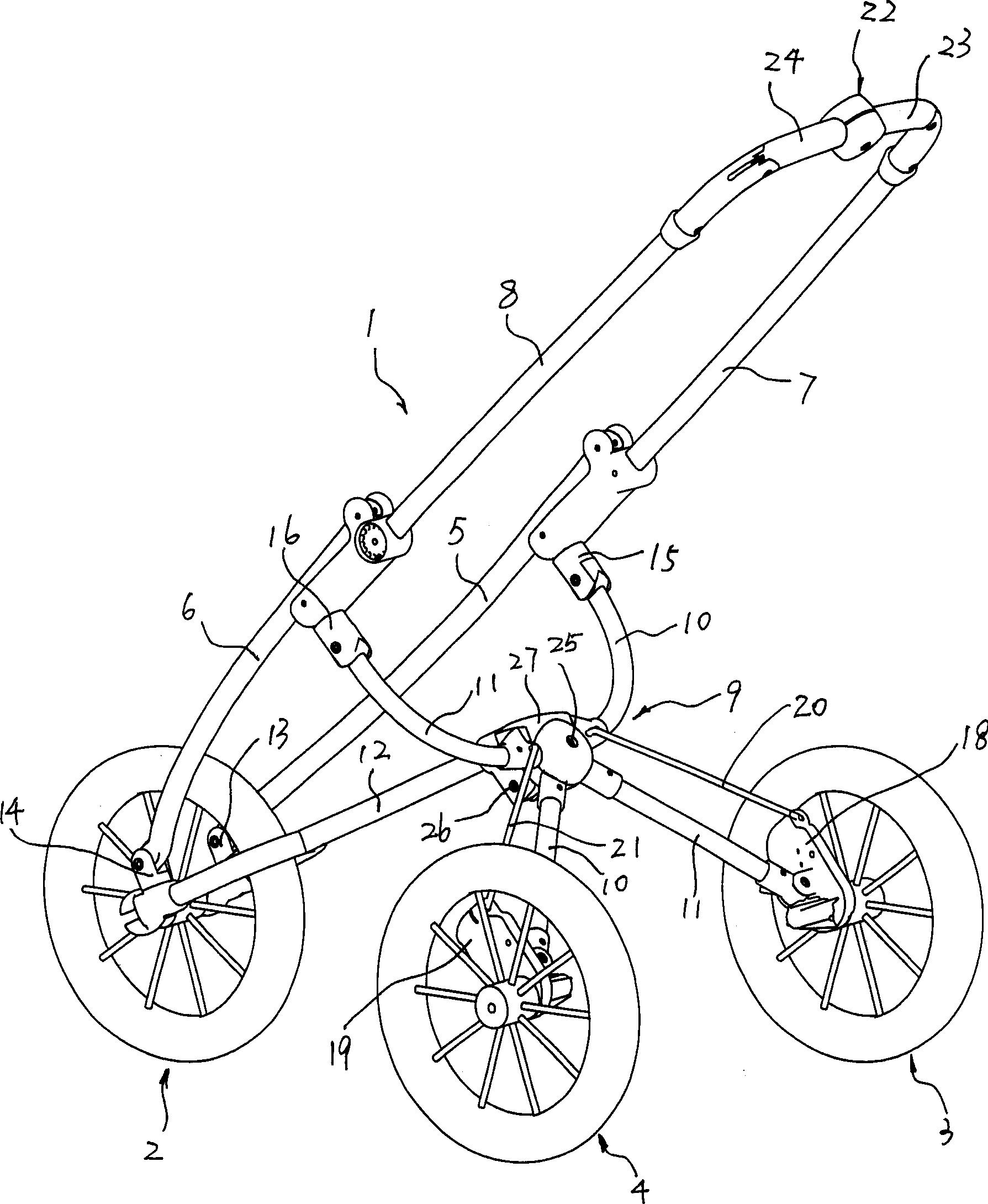
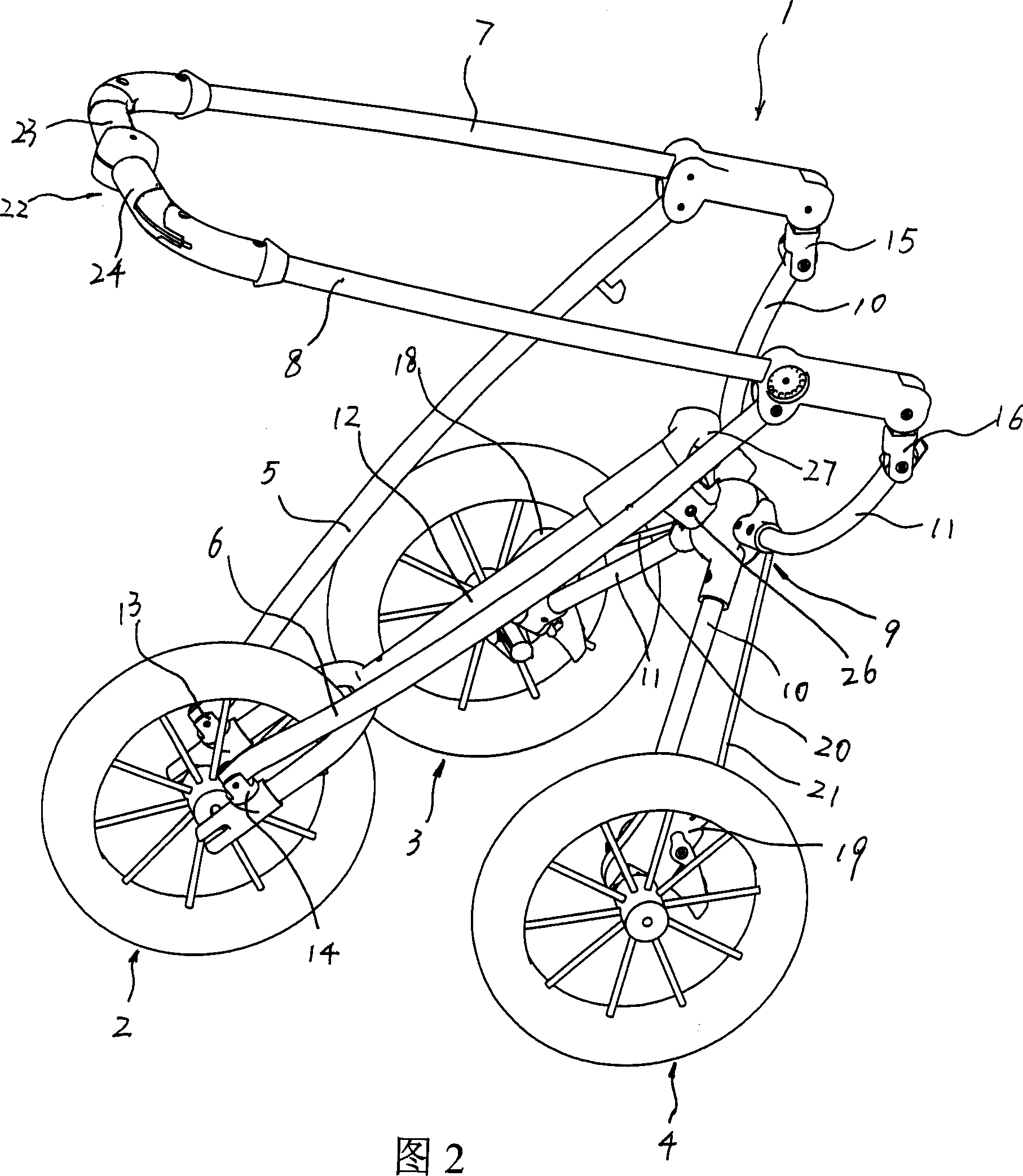
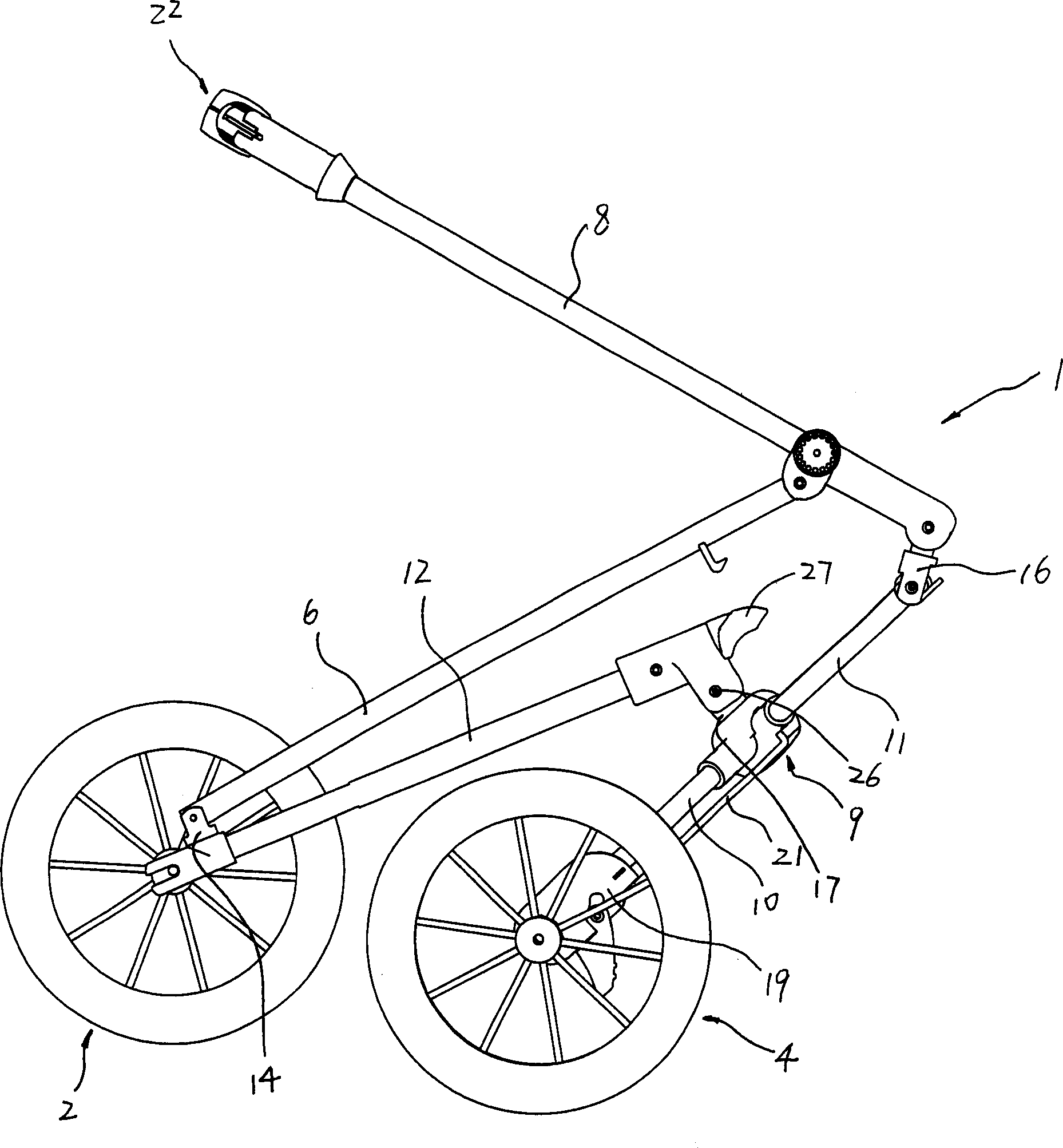
[0033] The first embodiment: as shown in the accompanying drawings, a baby stroller includes a stroller frame 1 for switching between an open state and a folded state;
[0034] The front wheel assembly 2 arranged at the lower front part of the cart frame 1;
[0035] The first rear wheel assembly 3 and the second rear wheel assembly 4 are respectively arranged on the left and right sides of the lower rear part of the cart frame 1;
[0036] The cart frame 1 includes an underframe 12;
[0037] The first front wheel bracket 5, the front end of the first front wheel bracket 5 and the front part of the underframe 12 are rotationally connected through a first swivel joint 13, and the first swivel joint 13 makes The front end of the first front wheel bracket 5 and the front of the chassis 12 can rotate at least in two intersecting plane directions;
[0038] The second front wheel bracket 6, the front end of the second front wheel bracket 6 is rotationally connected to the front port...
no. 2 example
[0044] The second embodiment: not shown, a baby stroller, including a stroller frame 1 for switching between an open state and a folded state;
[0045] The front wheel assembly 2 arranged at the lower front part of the cart frame 1;
[0046] The first rear wheel assembly 3 and the second rear wheel assembly 4 are respectively arranged on the left and right sides of the lower rear part of the cart frame 1;
[0047] The cart frame 1 includes an underframe 12;
[0048] The first front wheel bracket 5, the front end of the first front wheel bracket 5 is connected to the front part of the underframe 12 by a first rotating joint 13, and the first rotating joint 13 is first ball joint;
[0049] The second front wheel bracket 6, the front end of the second front wheel bracket 6 and the front part of the underframe 12 are ball-connected through a second rotating joint 14, and the second rotating joint 14 is second ball joint;
[0050] The first push rod 7, the lower part of the fir...
no. 3 example
[0054] The third embodiment: as attached figure 1 - attached Figure 6 As shown, in the third embodiment, on the basis of the first embodiment or the second embodiment, the contracting mechanism of the first rear wheel and the second rear wheel is added. The retracting mechanism includes a first rear wheel link 20 and a second rear wheel link 21 . The first rear wheel assembly 3 includes a first rear wheel joint 18, a first rear wheel disposed on the first rear wheel joint 18, the lower end of the second rear wheel bracket 11 is connected to the The first rear wheel joint 18 is pivotally connected, the first rear wheel joint 18 is also pivotally connected with the lower end of the first rear wheel link 20, the first rear wheel link 20 The upper end of the first rear wheel bracket 10 is pivotally connected with the upper part; the second rear wheel assembly 4 includes a second rear wheel joint 19, which is arranged on the second rear wheel joint 19 The second rear wheel, the...
PUM
 Abstract
Description
Claims
Application Information
 - Generate Ideas
- Intellectual Property
- Life Sciences
- Materials
- Tech Scout
- Unparalleled Data Quality
- Higher Quality Content
- 60% Fewer Hallucinations
Browse by: Latest US Patents, China's latest patents, Technical Efficacy Thesaurus, Application Domain, Technology Topic, Popular Technical Reports.
© 2025 PatSnap. All rights reserved.Legal|Privacy policy|Modern Slavery Act Transparency Statement|Sitemap|About US| Contact US: help@patsnap.com


