
Sewing machine

A technology for a sewing machine and a thread adjusting device, which is applied to sewing machine components, sewing equipment, program-controlled sewing machines, etc., can solve the problems of inability to form zigzag parallel parts, disorder and irregularity at the beginning of zigzag stitches, etc. The effect of stabilizing tension changes

Inactive Publication Date: 2012-07-04
JUKI CORP
View PDF1 Cites 0 Cited by
  • Summary
  • Abstract
  • Description
  • Claims
  • Application Information

AI Technical Summary

Problems solved by technology

[0009] On the other hand, when the auxiliary thread adjuster is arranged on the upstream side of the upper thread path and the main thread adjuster is arranged on the downstream side, since the path between the stitch forming part and the main thread adjuster is relatively short, although the The upper thread tension change based on changing the tension setting of the main thread adjuster quickly acts on the stitches, but because the stretching capacity of the upper thread on its path is small, it acts on the upper thread part of the stitch forming part. sharp change in tension
[0010] Especially when entering the parallel part from the end knot, the sharp increase of the upper thread tension will cause the start end of the zigzag stitch to be disordered, so that a beautiful zigzag parallel part cannot be formed.
[0011] On the other hand, when entering from the parallel part to the end knot, the tension of the upper thread decreases sharply. At this time, the expansion and contraction of the upper thread is suddenly released, forming a situation where the upper thread is stretched out more than the upper thread of the thread take-up lever. The state of the quantity, thus making the stitches disordered and not neat
In addition, the loop of the upper thread stretched out by excess is likely to be caught by the tip of the hook to cause double hanging of the thread, which easily leads to thread breakage.

Method used


Image

  • Sewing machine
  • Sewing machine
  • Sewing machine

Examples


Embodiment Construction

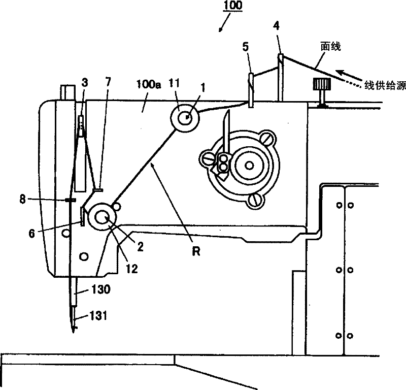
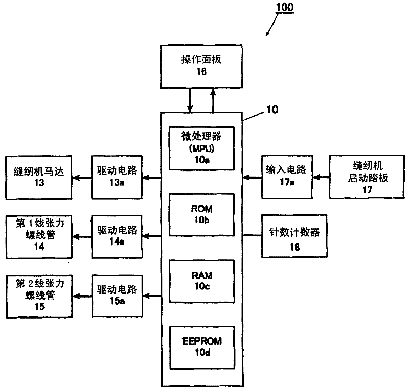
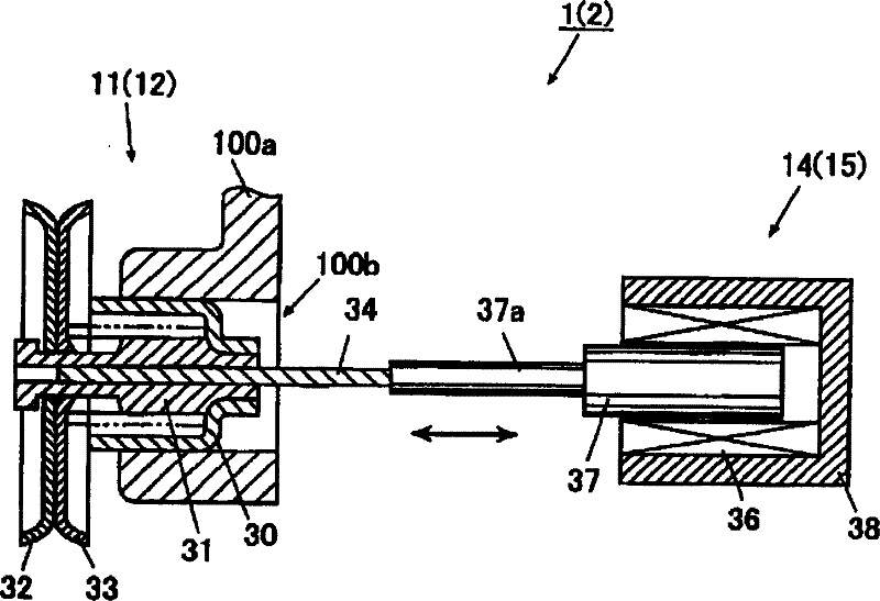
[0064] Below, combine Figure 1 to Figure 8 , the embodiment of the present invention will be described.

[0065] The sewing machine 100 of the present embodiment is an example of a buttonhole sewing machine in which the present invention is applied to form buttonhole stitches for buttonholes on a sewn object.

[0066] Such as figure 1 , figure 2 As shown, the sewing machine 100 has: a sewing machine motor 13 as a sewing machine drive source, a sewing machine start pedal 17 that drives the sewing machine motor 13 to rotate, a needle bar 130 that moves up and down as the sewing machine motor 13 is driven by rotation, and is fixed on Machine needle 131 on needle bar 130. In addition, the sewing machine 100 has a first thread adjusting device 1, a second thread adjusting device 2, a take-up thread arrangement, and a first thread adjusting device 1, a second thread adjusting device 2, and a thread adjusting device 1 arranged on the upper thread path R along which the upper th...


PUM


Abstract

The present invention is one kind of sewing machine with stable tension change. The sewing machine is provided with two thread regulating devices in the upper thread path, and each of the thread regulating devices has one thread regulator to apply tension to the upper thread and one thread tension solenoid to change the tension applied to the upper thread. One tension regulating and controlling device controls the motions of these two thread regulating devices for applying different tensions to the upper thread, so as to reach smooth and stable tension change.

Description

technical field [0001] The invention relates to a sewing machine with a plurality of thread regulators on the upper thread path. Background technique [0002] Conventionally, there are known sewing machines with the following structure, that is, two thread adjusting devices are arranged on the upper thread path, and one of the thread adjusting devices is configured to change the amount of thread given to the upper thread under the driving of the electric drive device during sewing. For the structure of tension (main thread adjuster), another thread adjustment device is configured to apply relatively weak tension to the upper thread under the action of a spring (sub-thread adjuster, pretension) (for example, refer to Patent Document 1). [0003] The two thread adjusting devices constituting the above-mentioned main thread adjusting device and sub-thread adjusting device are configured such that the thread adjusting device of the main thread adjusting device is arranged on the...

Claims


Application Information

Patent Timeline
Patent Type & Authority Patents(China)
IPC IPC(8): D05B47/00
CPCD05B19/12D05B47/04D05B63/00D05B69/30
Inventor 绪方孝宏
Owner JUKI CORP
Learn More