Microcomputer

A technology of microcomputers and transmitters, which is applied in signal transmission systems, instruments, non-electrical signal transmission systems, etc. It can solve the limitations of shell design, miniaturization of printed circuit boards, and the inability to realize the miniaturization of the shell of remote control transmitters and Thinning and other issues, to achieve the effect of simplifying the installation process and reducing the number of installation parts

Inactive Publication Date: 2006-11-29
SMK CO LTD
View PDF0 Cites 1 Cited by
  • Summary
  • Abstract
  • Description
  • Claims
  • Application Information

AI Technical Summary

Problems solved by technology

[0015] Also, since there are many parts to be mounted, a predetermined mounting area is required on the printed circuit board to be mounted, and the miniaturization of the printed circuit board itself is limited, and because the vibrato...

Method used


Image

  • Microcomputer
  • Microcomputer
  • Microcomputer

Examples


Embodiment Construction

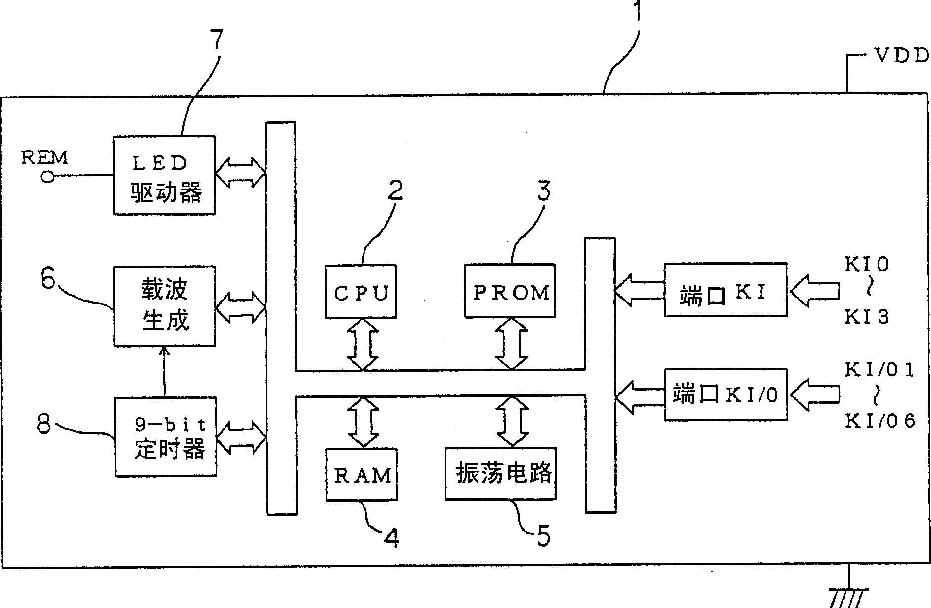
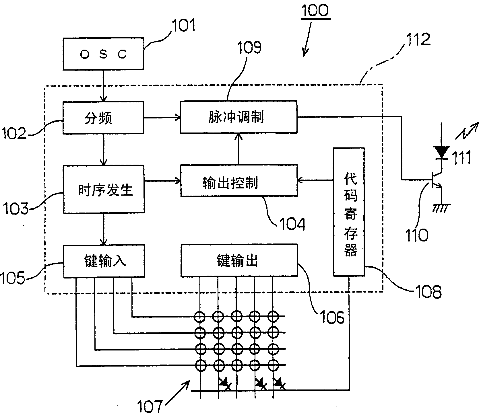
[0052] Below, use figure 1 and figure 2 The microcomputer 1 of the present invention will be described. figure 1 It is a block diagram showing main parts of the remote control transmitter 10 in which the microcomputer 1 is installed.

[0053] The action of remote control transmitter 10 is to utilize microcomputer 1 to control, as figure 1 As shown, a keyboard switch 12 composed of a plurality of keys 11, 11... is connected to the microcomputer 1. The keyboard switch 12 is an output lead pattern 13A drawn from the input and output signal terminals of KI / O1 to KI / O6 of the microcomputer 1 and an input lead pattern 13B drawn from the input signal terminals of KI0 and even KI3, which are insulated from each other and arranged in a matrix On a printed wiring board (not shown), a pair of switch electrodes are respectively connected to the output lead pattern 13A and the input lead pattern 13B intersecting at crossing positions to form the key 11 . The pair of switch electrod...


PUM


Abstract

The invention provides a microcomputer manufacturing remote control transmitter (10) corresponding to various controlled equipment in a short time. The solve method is to set up programming ROM (3) which can overwrite and store utility programs, RC tank circuits (6), and an energizing circuit (7) of light items which drives and controls infrared light items (16) in the microcomputer (1) handled the movement of remote control transmitter (10), and to make the main units of the remote control transmitters (10) of different specifications joint use one IC array.

Description

technical field [0001] The present invention relates to a microcomputer for controlling the action of a remote control transmitter. More specifically, it relates to a microcomputer with a built-in programmable ROM (Programmable Read Only Memory). The programmable ROM can be programmed on site to control the action of a remote control transmitter. s application. Background technique [0002] A conventional remote control transmitter (Patent Document 1) of a controlled device such as a remote control television receiver is provided with a keyboard switch composed of a plurality of keys, and once one of the keys is input and operated, the control corresponding to the operated key is included. The infrared control signal of the command will emit light from the infrared light-emitting element, and the controlled device that receives the infrared control signal will perform an action according to the control command. [0003] [Patent Document 1] Patent No. 3153084 (column 3, colu...

Claims


Application Information

Patent Timeline
IPC IPC(8): G08C23/04H03J9/06
Inventor 冈村量佐藤文男
Owner SMK CO LTD
Why Eureka
Try Eureka