
Power supply switching device for household electrical appliance

A switching device and power switching technology, applied in circuits, semiconductor devices, transistors, etc., can solve the problems of power consumption, energy waste, standby power consumption, etc., and achieve the effect of zero standby power consumption

Active Publication Date: 2010-05-26
HAIER GRP CORP +1
View PDF3 Cites 0 Cited by
  • Summary
  • Abstract
  • Description
  • Claims
  • Application Information

AI Technical Summary

Problems solved by technology

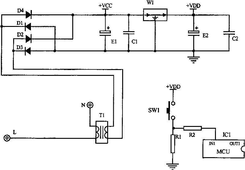
[0003] In the current control device of household appliances, the state of the power switching device SW1 is scanned by the single-chip microcomputer, but because the single-chip microcomputer can only sense whether the power button is pressed when it is charged and in the working state, there is still a standby state when the household appliance is not working. Power consumption, consumes a large amount of electric energy, causing serious waste of energy

Method used


Image

  • Power supply switching device for household electrical appliance
  • Power supply switching device for household electrical appliance
  • Power supply switching device for household electrical appliance

Examples


no. 1 example

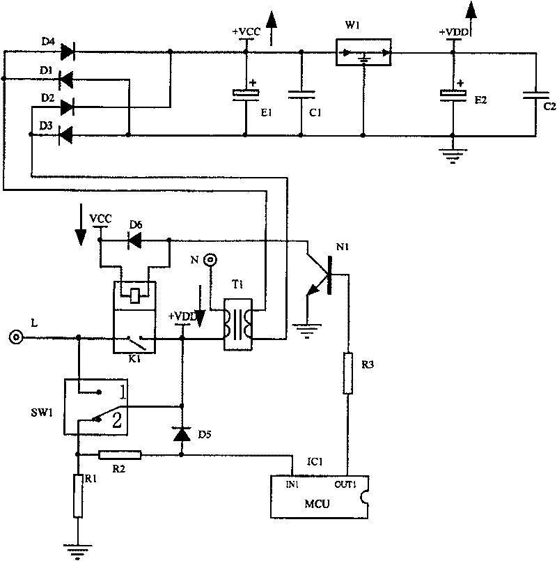
[0038] Embodiment 1: In this embodiment, the switching device is an elastic switch, which acts as a power button for starting and shutting down the washing machine, and the controlled device is a relay.

[0039] image 3It is a schematic diagram of the power switching device of the washing machine. K1 is a relay, T1 is a transformer, L is the live wire of the plug, N is the neutral wire of the power, SW1 is a power key switch, the SW1 includes a normally open contact 1 and a normally closed contact 2, and one end of SW1 and relay K1 It is connected to the live wire L of the plug, and the other end is connected to the primary side of the transformer T1; the output voltage of the secondary side of the transformer T1 passes through the rectifying device composed of rectifying diodes D1, D2, D3, D4 and the voltage stabilizing device W1, and then becomes the power supply VDD of the microcontroller MCU , Relay power supply VCC and load power supply. In order to enable the signal i...


PUM


Abstract

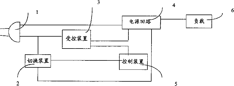
The invention discloses an electrical source shifter, which consists of power plug and power return circuit, wherein the electrical source shifter has the shifter which connects power plug and power return circuit; the first branch line is composed of shifter and power circuit; the shifter connects controlled device; the second branch line is composed of controlled device and shifter; when the shifter connests the first branch line, the control device controls controlled device to connect the second branch line; the shifter cuts the first branch line; the control device controls controlled device on-off by checking shifter voltage.

Description

technical field [0001] The invention relates to a household appliance with an electric control board, in particular to a power switching device for the household appliance with an electric control board. Background technique [0002] Household appliances existing on the market generally have an electric control board. When the power plug is inserted into a charged socket, the electric control board is charged, and then the working state of the household appliance is controlled by the power switching device of the household appliance. figure 1 It is a circuit diagram of a power switching device for a household appliance with an electric control board. The primary side of the transformer T1 is respectively connected to the live line L and the neutral line N of the power plug, and the secondary side will input the voltage after the rectification circuit composed of diodes D1, D2, D3 and D4 and the voltage stabilization circuit W1 into the single-chip MCU, and then the single-ch...

Claims


Application Information

Patent Timeline
Patent Type & Authority Patents(China)
IPC IPC(8): H03K17/60
Inventor 孙奇辉李志罡李莉朱旬
Owner HAIER GRP CORP
Learn More