
Device and method for implementing patterns on the narrow side of the plate workpieces

A plate-shaped workpiece, narrow technology, applied in the direction of printing devices, manufacturing tools, wood processing equipment, etc., can solve the problems of high work cost and standby time, and achieve the effects of minimizing misprinting, improving pattern quality, and saving printing materials

Active Publication Date: 2006-11-01
豪迈木材加工系统公司
View PDF5 Cites 3 Cited by
  • Summary
  • Abstract
  • Description
  • Claims
  • Application Information

AI Technical Summary

Problems solved by technology

When the height of the narrow side to be printed varies, this results in considerable operating costs and corresponding standby times

Method used


Image

  • Device and method for implementing patterns on the narrow side of the plate workpieces
  • Device and method for implementing patterns on the narrow side of the plate workpieces
  • Device and method for implementing patterns on the narrow side of the plate workpieces

Examples


Embodiment Construction

[0024] Preferred embodiments of the present invention will be described in detail below in conjunction with the accompanying drawings.

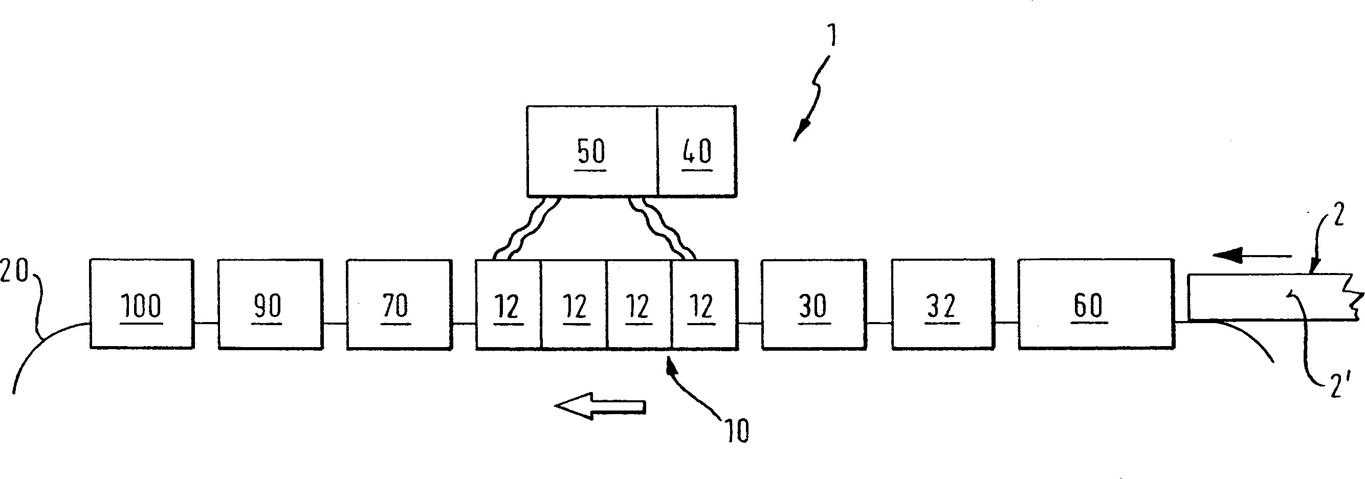
[0025] figure 1 A side view of a first embodiment of the device according to the invention is schematically shown. The shown device 1 is used for printing a pattern on the narrow side 2' of a plate-shaped workpiece 2, which is preferably substantially made of wood or wood and is embodied, for example, as a furniture part, a kitchen worktop or the like. It should be noted that the present invention is not limited to printing patterns on narrow sides, and in principle, the present invention is also suitable for printing patterns on wide surfaces of plate-shaped workpieces.

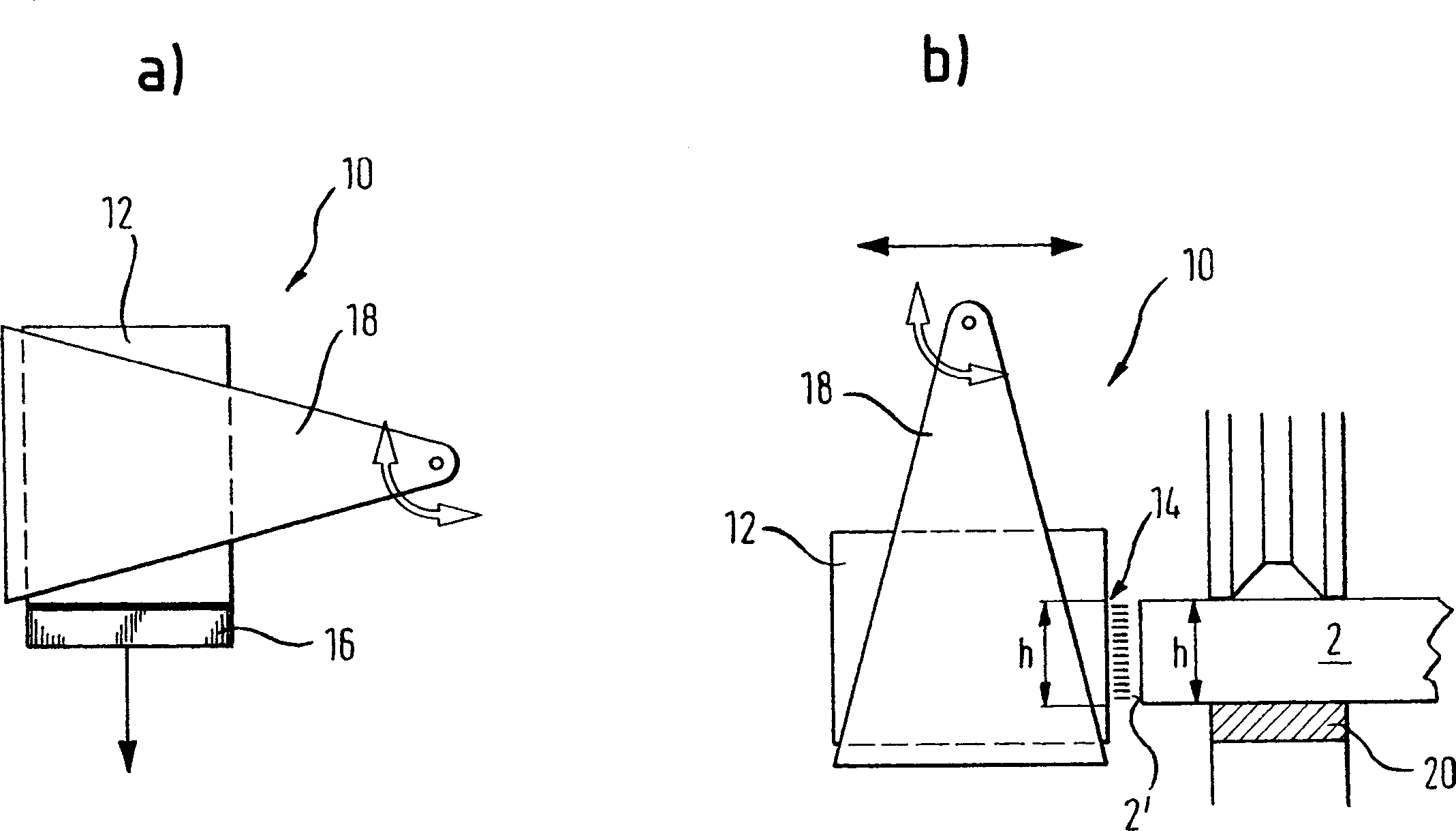
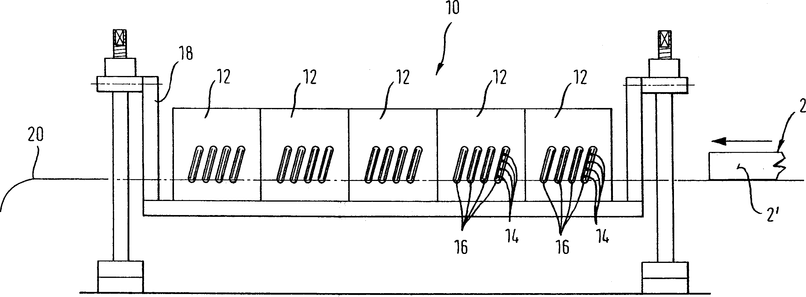
[0026] The device 1 comprises a stationary printing unit 10 which, in the present embodiment, has four inkjet print heads 12 . One printhead ejects black, one printhead magenta, one printhead yellow, and one printhead cyan, which makes sense for multi-color patterns. Eac...


PUM


Abstract

The invention discloses a pattern exerting device (1) and method of narrow side (2') of board-shaped workpiece (2) through wood, which comprises the following parts: static printing unit (10), which possesses multiple static ink-injecting heads (12) with multiple sprayers (14); transmitting device (20), which transmits workpiece (2) to printing unit (10); detecting devices (30, 32) on the upstream of printing unit, which detect narrow side (2') and or position and or transmitting speed of workpiece (2) on the transmitting device (20); reserving device (40), which stores image data of narrow side (2'); control device (50), which interconnects printing head (12), detecting devices (30, 32) and reserving device (40) to spray ink from sprayer (14) in the printing region (D), wherein the height of printing region equals the height of pattern narrow side (2') relatively.

Description

technical field [0001] The invention relates to a device for applying a pattern on the narrow side of a plate-shaped workpiece, preferably substantially consisting of wood or wood, having a stationary printing unit with at least one stationary inkjet print head, The or each print head has nozzles for ejecting ink, and the device also has a transport device by means of which the workpiece can be transported to the printing unit. Background technique [0002] A printing device of the type mentioned at the outset is known, for example, from DE 20 2004 000 662 U1. In such a device, the print head is adjusted and adjusted to the height of the narrow side to be printed by means of an adjustment device from before the printing operation starts. This results in considerable operating costs and corresponding standby times when the height of the narrow side to be printed varies. [0003] WO 02 / 00449 also discloses a printing device with a printing head which, during the printing pro...

Claims


Application Information

Patent Timeline
IPC IPC(8): B41J3/407B41J2/07B41J11/00
CPCB41J3/4073B41J11/0095B27D5/003B41J11/00214
Inventor 库尔特·卡尔姆巴赫约翰内斯·施密德卡尔·弗赖
Owner 豪迈木材加工系统公司
Learn More