
Two-for-one twisting mechanism

A technology of frame and yarn guide device, applied in textiles and papermaking, etc., can solve the problems of hairiness, poor yarn strength, yarn breakage, etc.

Inactive Publication Date: 2006-10-25
屠建文
View PDF0 Cites 6 Cited by
  • Summary
  • Abstract
  • Description
  • Claims
  • Application Information

AI Technical Summary

Problems solved by technology

The yarn guide device includes a yarn guide bracket. In actual work, the yarn will touch the yarn guide bracket, and the contact between the high-speed rotating yarn and the yarn guide bracket will produce hairiness, resulting in poor yarn strength and prone to hair loss. broken yarn

Method used

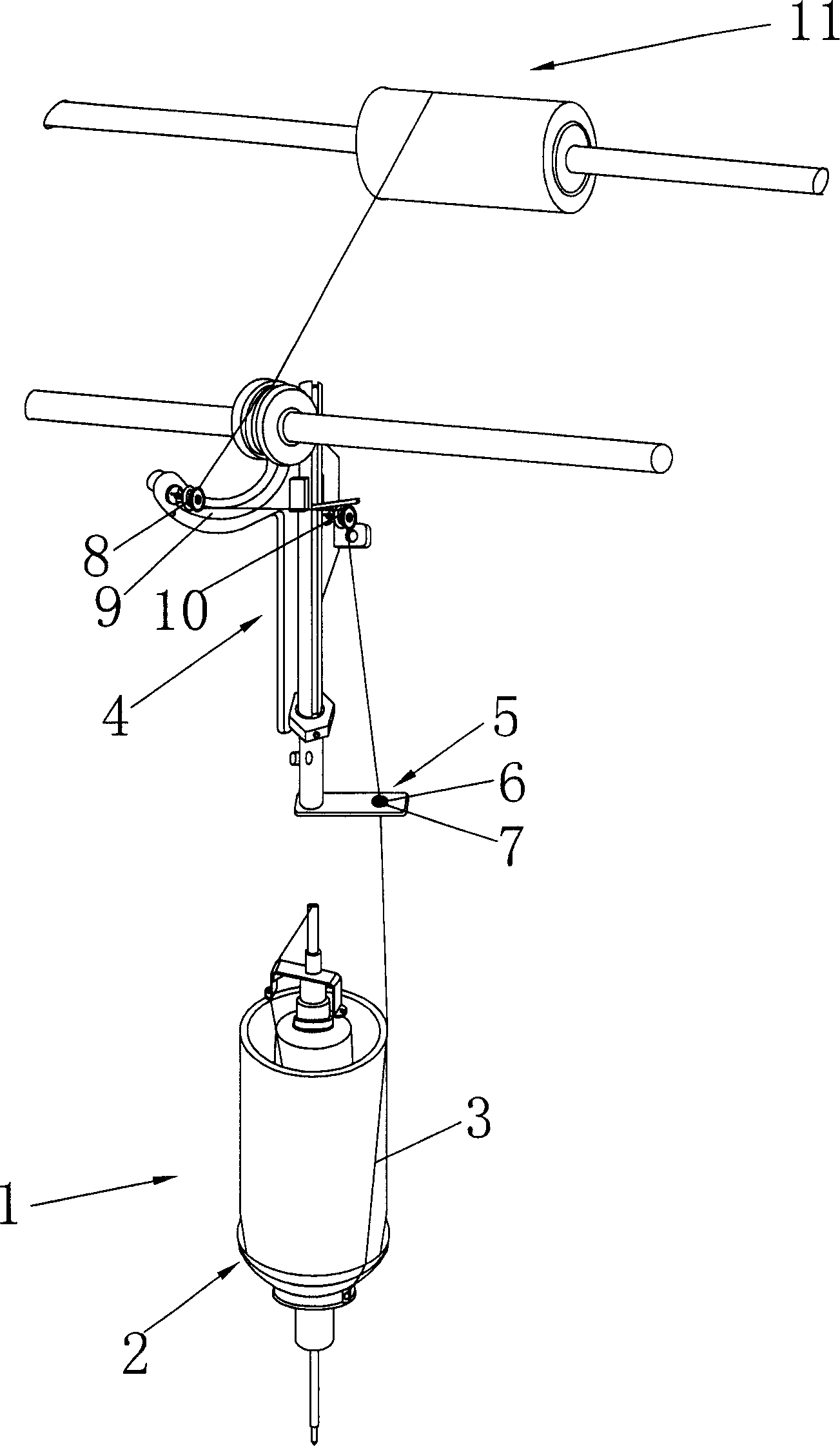

Image

  • Two-for-one twisting mechanism
  • Two-for-one twisting mechanism
  • Two-for-one twisting mechanism

Examples


Embodiment Construction

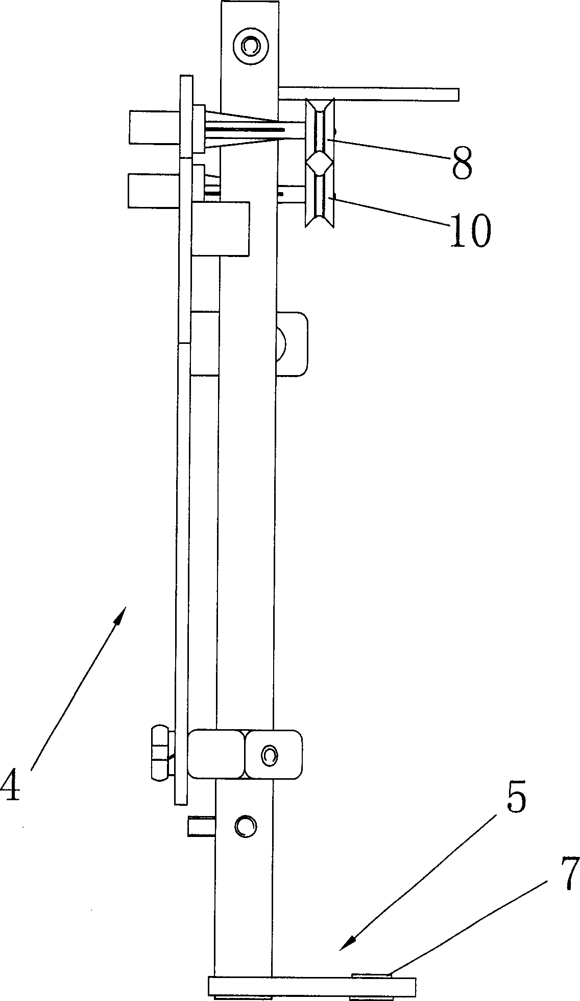
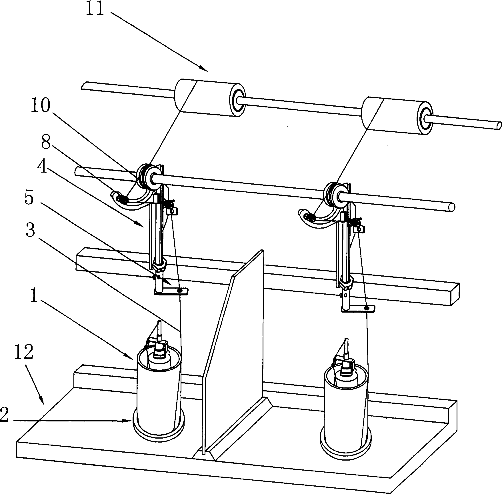
[0013] See attached figure 1 - attached Figure 4 As shown, a two-for-one twisting mechanism includes a frame 12, a spindle turntable 2 rotatably arranged on the frame 12, a yarn storage drum 1 arranged on the spindle turntable 2, and a The yarn guiding device and the winding device 11 on the frame 12, the described yarn guiding device is located between the yarn storage drum 1 and the winding device 11, and the described yarn guiding device comprises a yarn guiding bracket 4, which is arranged on the The yarn threading plate 5 on the yarn guide bracket 4, the threading plate 5 is provided with a bearing 7, the bearing 7 includes a relatively rotatable inner ring 14 and an outer ring 13, and the yarn 3 passes through the inner ring 14, And the outer ring 13 is fixed on the said yarn threading plate 5 . In the embodiments shown in the drawings, the yarn threading plate 5 is provided with a mounting hole 6, and the bearing 7 is arranged in the mounting hole 6.

[0014] In the...


PUM


Abstract

The double twisting framework includes the engine frame, the spindle dial running intercalated on the said engine frame, the guiding yarn setting and the winding setting intercalated on the said engine frame, the said guiding yarn is located between the storing yarn canister and the winding yarn setting, the said guiding yarn setting includes the guiding yarn bracket, the threading yarn board is located on the said guiding yarn bracket, the bearing is located on the said threading yarn board. In the practice appliance, the yarn is missive pass the spindle dial from the storing yarn canister, the spindle dial is tail-wagging, the yarn is tail-wagging drive by the spindle dial to realize the twisting and coiling handle of the yarn, when the yarn passes the guiding yarn setting, the yarn is drilled through the bearing, then the yarn is coiled the tension bearing piece, the yarn can drive the inside track of the bearing to eddy, so the tatty degree of the yarn can be depressed, the filoplume produced from the yarn is reduced to ensure the intension of the yarn and reduce the breaking yarn phenomenon.

Description

technical field [0001] The invention relates to a two-for-one twister. Background technique [0002] The existing two-for-one twisting machine comprises a frame, a spindle turntable arranged on the frame, a yarn storage bobbin arranged on the spindle turntable, a yarn guiding device and a winding device arranged on the frame, and yarns are stored in the yarn storage bobbin. There is usually a yarn outlet on the spindle turntable, the yarn passes through the yarn outlet, and is taken up by the winding device after passing through the yarn guide device, and the spindle turntable rotates at a high speed under the action of the driving device, so that the yarn is Driven by the spindle turntable, it rotates around the yarn storage drum at high speed, so as to realize the twisting operation of the yarn. The yarn guide device includes a yarn guide bracket. In actual work, the yarn will touch the yarn guide bracket, and the contact between the high-speed ...

Claims


Application Information

Patent Timeline
Patent Type & Authority Applications(China)
IPC IPC(8): D01H7/86
Inventor 屠建文
Owner 屠建文
Learn More