
Pressure gauge attachable to inflator

A manometer and pump technology, used in inflatable body pressure measurement, fluid pressure measurement, measurement devices, etc.

Active Publication Date: 2006-10-04
TOPEAK
View PDF0 Cites 5 Cited by
  • Summary
  • Abstract
  • Description
  • Claims
  • Application Information

AI Technical Summary

Problems solved by technology

[0005] The purpose of the manometer connected to the air pump of the present invention is to overcome the deficiencies and defects of the prior art. The technical problem to be solved is that the existing manometer cannot provide the user with the effect of measuring while inflating , so it is improved

Method used


Image

  • Pressure gauge attachable to inflator
  • Pressure gauge attachable to inflator
  • Pressure gauge attachable to inflator

Examples


Embodiment Construction

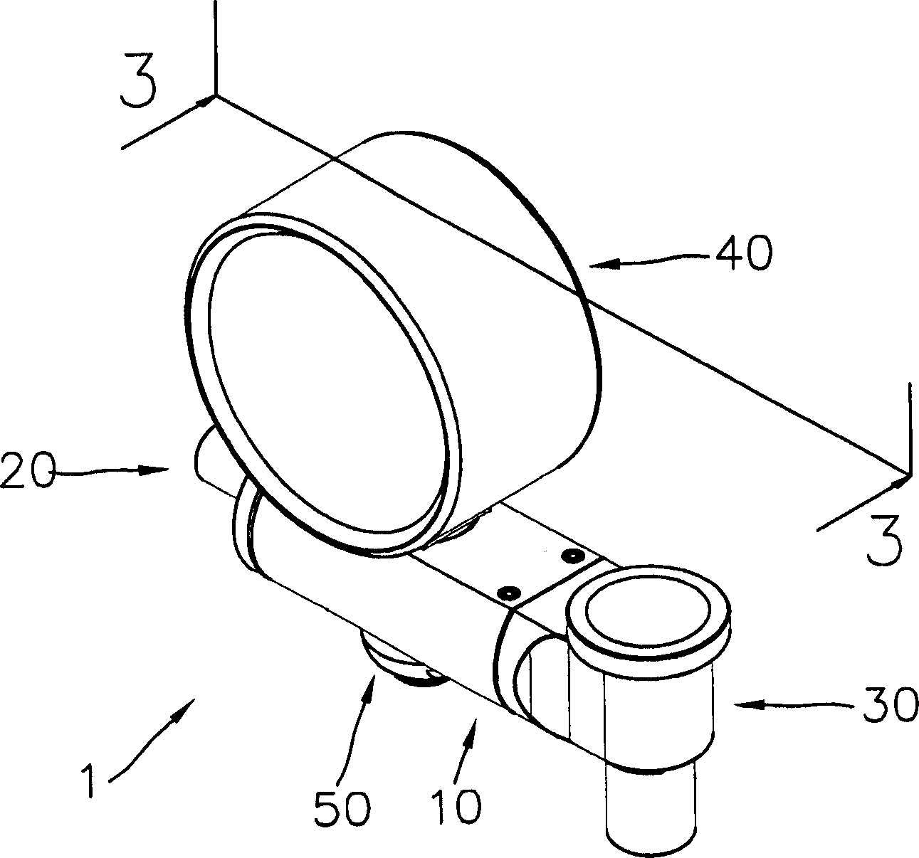
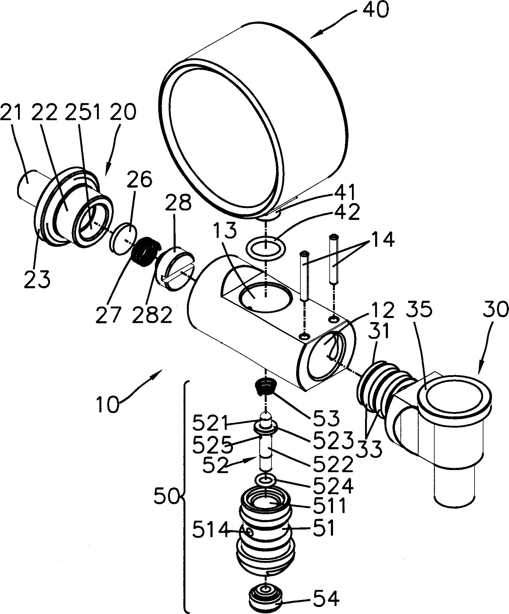
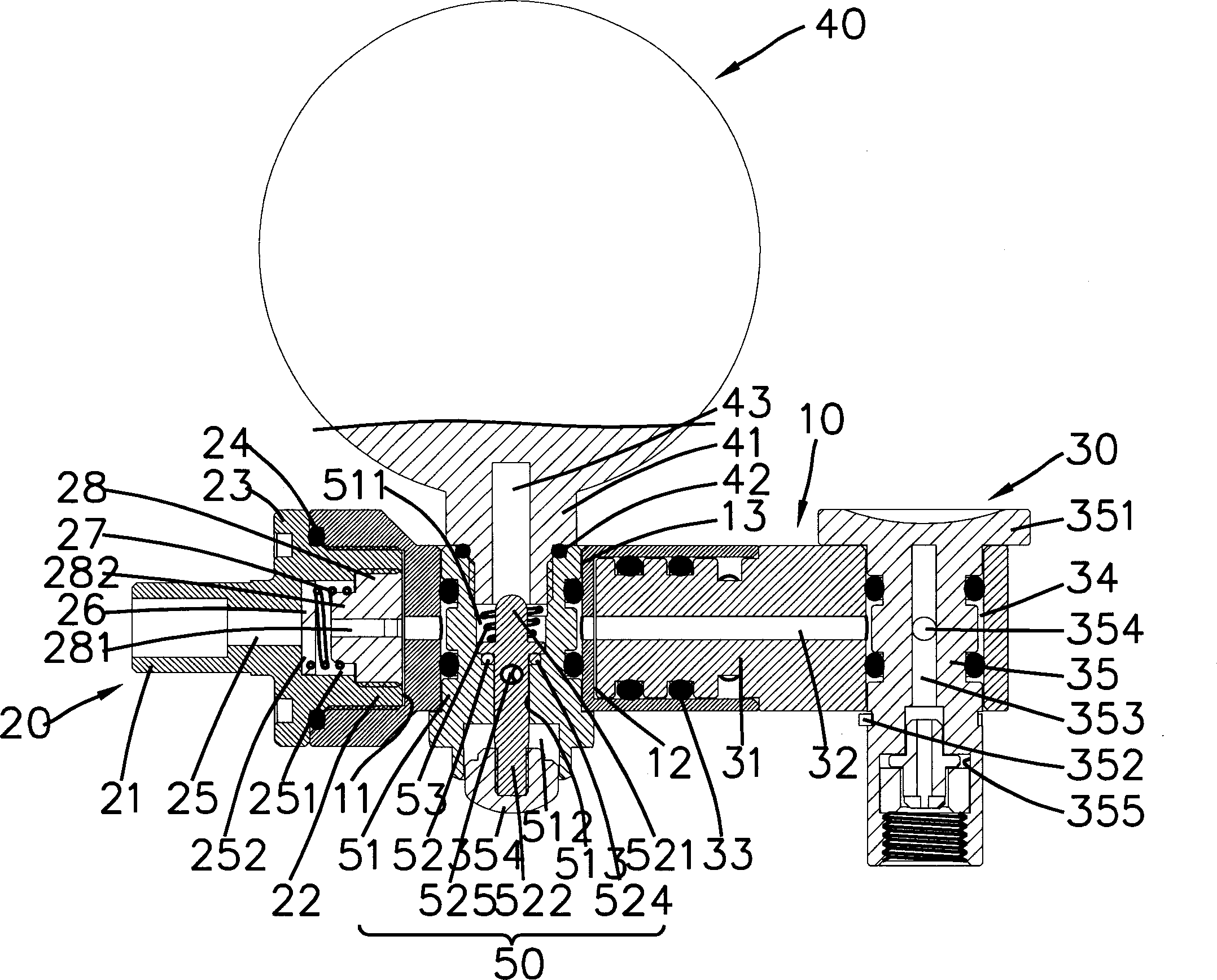
[0043] refer to Figure 1 to Figure 3 , the pressure gauge 1 of the present invention has a first end and a second end, the first end is set as a coupling device 20, which can be combined with the gas outlet end of the pump (not shown in this figure), and the second end is There is a connection device 30 which can be connected to the gas nozzle of the object to be inflated (not shown in this figure), and an airway (not shown in this figure) opened at both ends is further provided in the manometer 1, and an appropriate place in the airway The group is provided with a pressure gauge 40 .

[0044] The pressure gauge 1 includes a body 10, the first end and the second end of the body 10 are provided with circular grooves 11, 12, and the body 10 is further provided with a radial hole between the two ends 13. Both the above two grooves 11 and 12 can communicate with the hole 13.

[0045] The groove 11 at the first end of the body 10 can be combined with a coupling device 20; the co...


PUM


Abstract

The related manometer fit to connect an inflator comprises: a first end to combine the gas outlet of inflator, a second end connected to the target gas inlet, a gas channel between two ends, and a piezometer in proper position of the channel to measure the pressure after stopping operation and show result on the manometer. This invention has well practical value.

Description

technical field [0001] The invention relates to a manometer, in particular to a manometer which can be connected to an air pump. Background technique [0002] Existing pressure gauges at present, as shown in the applicant's previous application for TW announcement No. 391519 "tire pressure gauge (two)" patent case, it mainly includes: a head 10, a handle 20 and a pressure measurement Mouth 30; where the head 10 is provided with a display 11 to display tire pressure data, and the pressure measuring mouth 30 has a turntable 50 inside, which can be converted and used for American air nozzles by pulling a switching key 40 with French valve. [0003] Although the above-mentioned manometer has the excellent effect of being converted to adapt to different valves, it can only be used for general pressure measurement. If the user wants to do the work of inflating, he must first remove the manometer. Under such circumstances, such repeated loading and unloading of manometers and pum...

Claims


Application Information

Patent Timeline
Patent Type & Authority Applications(China)
IPC IPC(8): G01L19/00G01L17/00
Inventor 荘士文
Owner TOPEAK
Learn More