
Method for forming hollow plastic products and device therefor

A technology of plastic products and molding methods, which is applied in the field of controllable overflow cavity, can solve the problems of product strength reduction, waste of gas energy, product surface air marks, etc., and achieve the goal of improving product qualification rate, prolonging equipment life, and prolonging mold life Effect

Inactive Publication Date: 2006-09-27
BEIJING CHN TOP MACHINERY
View PDF0 Cites 23 Cited by
  • Summary
  • Abstract
  • Description
  • Claims
  • Application Information

AI Technical Summary

Problems solved by technology

Since the volume of the melt discharged before testing and molding cannot be accurately calculated
Therefore, it is necessary to repeatedly adjust the volume of the overflow cavity after the initial or subsequent model inspection test, which brings great inconvenience to the mold processing, and the change of the plastic material, the level of the melt temperature in the process, and the change of the molding machine parameters , the temperature of the cavity, the interval between the discharge start time of the gas pushing the molten plastic in the thicker position of the cavity and the injection time of the plastic, and the length of the discharge time all affect the amount of the discharge material, that is, the volume of the overflow cavity. The connection between the flow cavity and the cavity is connected through a small channel. The general control valve device is composed of a small plunger that cuts off the small channel, its control device, and the control system. The control part can move the position of the small plunger to control the small channel. In the production process, the plastic melt forms a solidified layer a

Method used


Image

  • Method for forming hollow plastic products and device therefor
  • Method for forming hollow plastic products and device therefor
  • Method for forming hollow plastic products and device therefor

Examples


Embodiment Construction

[0019] Below in conjunction with accompanying drawing, feature of the present invention and other relevant features are described in further detail:

[0020] In this embodiment, a plate product with a product thickness of 2-6 mm is used for illustration.

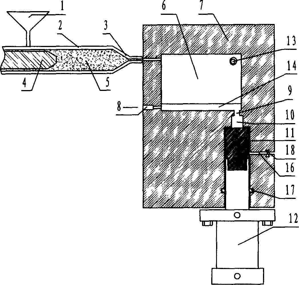
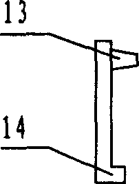
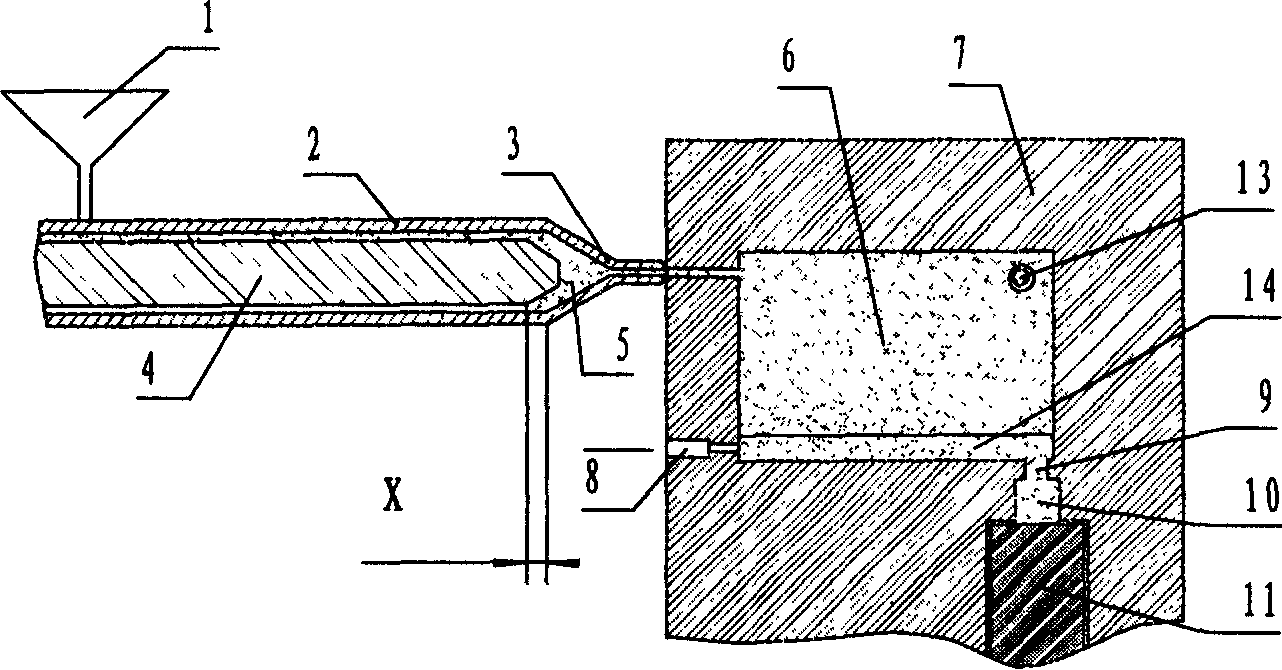
[0021] see figure 1 The middle mark 5 represents the molten plastic in the barrel of the injection molding machine, which is any kind of thermoplastic material that can be used for injection molding; the mark 1 represents the storage barrel of the injection molding machine; 2 represents the injection barrel of the injection molding machine; the mark 4 represents The inner screw of the injection barrel; the mark 3 represents the nozzle; the injection molding machine can be any type of injection molding machine, such as screw type or rod plug type; the mark 6 represents a mold cavity; the cavity 6 can be any traditional injection molding The cavity of the mold; the number 7 indicates the mold; the numbers 9 and 10 respectivel...


PUM


Abstract

The present invention relates to hollow plastic product forming process and device, and is especially gas assisted injection forming process for producing sheet type plastic product with structural rib board and the device, controllable flash chamber. The forming process includes at least: injecting molten plastic into inner cavity of mold, further injecting after filling the inner cavity to pressurize, controlling the piston of the flash chamber to withdraw some interval, introducing pressurizing gas to the molten plastic inside the cavity, pushing the molten plastic with the screw of the plastic injecting machine into the controllable flash chamber, controlling the gas pressure and piston shift to make gas enter to the relatively thick part inside the mold cavity, cooling plastic inside the mold cavity while controlling the piston shift, and making gas flow into inside of the plastic product to speed cooling. The present invention has the advantages of no shrinkage and crack in the thicker part of the product, high production efficiency, etc.

Description

technical field [0001] The present invention relates to a method for forming hollow plastic products and related devices, in particular to a method for producing thin-plate plastic products containing structural ribs using gas-assisted injection molding technology and related devices—controllable overflow cavity. technical background [0002] Ernst Friederich of Rohm GmbH in Germany was the first to invent the gas-assisted injection molding process. The patent No. 2501314 disclosed in German patent literature in 1975 is a molding method for making thermoplastics into hollow products by injection molding. The method disclosed in this patent literature includes injecting sufficient molten material into the prepared above-mentioned In the mold of the hollow product, the pressurized gas is also injected into the molten material through the hole on the nozzle to make the molten material fully contact with the inner surface of the mold. Then, in the above-mentioned mold, the hol...

Claims


Application Information

Patent Timeline
IPC IPC(8): B29C45/57B29C45/76B29C45/17B29L22/00
CPCB29C45/56B29C45/1711
Inventor 赵青松桓锁成范汝富
Owner BEIJING CHN TOP MACHINERY
Learn More