
Plastic ball valve

A technology for plastic ball valves and valve stems, which is applied to valve devices, cocks including cut-off devices, mechanical equipment, etc. It can solve problems such as high friction between seals and valve balls, large wear of seals and valve balls, and large switching torque , to achieve the effect of increasing the amount of elastic deformation, small switching torque and small wear

Inactive Publication Date: 2006-09-13
戴长虹 +1
View PDF0 Cites 5 Cited by
  • Summary
  • Abstract
  • Description
  • Claims
  • Application Information

AI Technical Summary

Problems solved by technology

[0002] The plastic ball valves currently used are generally single valve stems, using PTFE seals, relying on the tight contact between the PTFE seals and the valve ball under compressive stress to achieve sealing, so the friction between the seal and the valve ball Large force, resulting in large switching torque, large wear of seals and valve balls, and short service life

Method used


Image

  • Plastic ball valve

Examples


Embodiment Construction

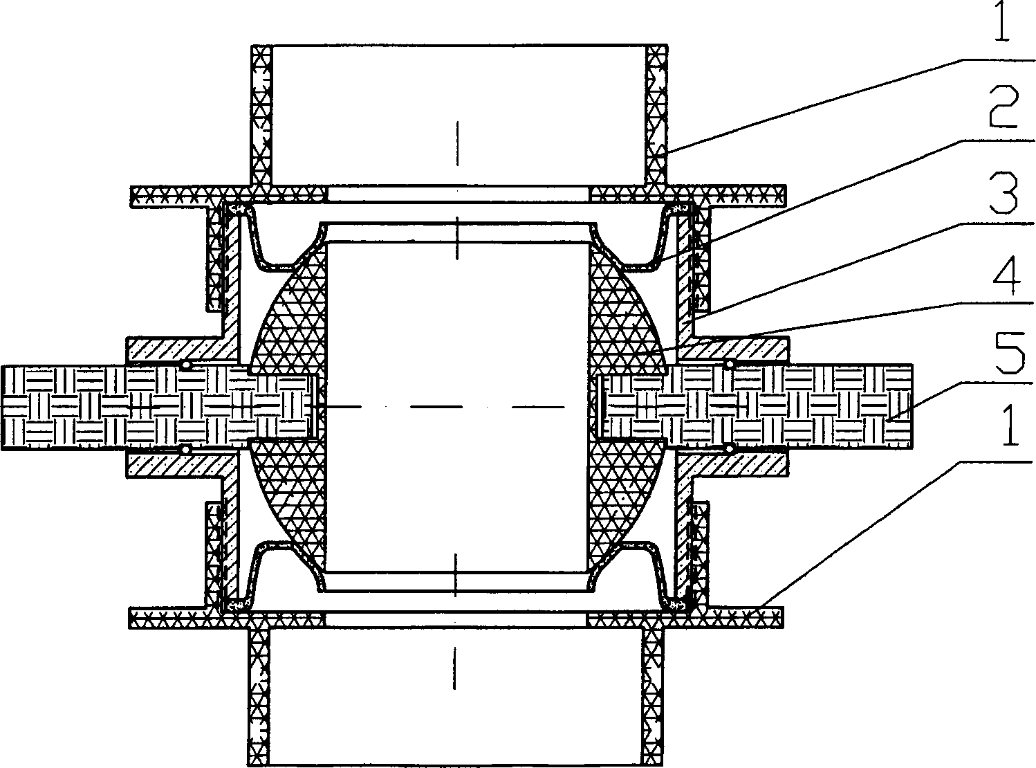
[0008] refer to figure 1 , the plastic ball valve is composed of end cover (1), seal (2), valve body (3), valve ball (4) and valve stem (5), etc., end cover (1), valve body (3), valve ball (4) and valve stem (5) are all used ABS engineering plastics injection molding, and seal (2) is made with polyurethane elastomer, and valve stem (5) place is installed rubber sealing ring, plays the effect of sealing and positioning to valve stem. The valve stem and the valve ball are connected by a wedge groove, the end cover and the valve body are connected by threads, the seal is fixed between the end cover and the valve body, and the inner ring of the seal is in close contact with the valve ball. The ball valve can be opened by manual, pedal and electric methods, and a corresponding switch device is required.


PUM


Abstract

The invention is a plastic ball valve, comprising end cover, valve body, valve ball, sealing member, etc, and characterized by adopting lip seal ring and double valve rod structure. And it has advantages of simple structure, convenient to make, good sealing effect, small turn-on and turn-off moment, low abrasion of valve ball and sealing member, long service life, low failure rate, etc.

Description

technical field [0001] The invention relates to a plastic ball valve, in particular to a plastic ball valve with low switching torque. Background technique [0002] The plastic ball valves currently used are generally single valve stems, using PTFE seals, relying on the tight contact between the PTFE seals and the valve ball under compressive stress to achieve sealing, so the friction between the seal and the valve ball The force is large, resulting in large switching torque, large wear of seals and valve balls, and short service life. Contents of the invention [0003] The purpose of the present invention is to provide a double-stem plastic ball valve with small switching torque, small wear of the seal and valve ball, and long service life. [0004] The plastic ball valve of the present invention is mainly composed of an end cover, a seal, a valve body, a valve ball, a valve stem and the like. The valve ball is fixed in the center of the valve body through two valve ste...

Claims


Application Information

Patent Timeline
IPC IPC(8): F16K5/06
Inventor 戴长虹张宝宝马贺利
Owner 戴长虹
Learn More