Crank angle detection device and ignition timing control device for internal combustion engine

A crank angle and detection device technology, which is applied in the direction of electric spark ignition controller, engine ignition, engine control, etc., can solve the problems that the initial detonation timing of the reverse rotation of the engine cannot be avoided, and the crank angle cannot be correctly determined, etc.

Inactive Publication Date: 2006-08-16
KEIHIN CORP
View PDF3 Cites 14 Cited by
  • Summary
  • Abstract
  • Description
  • Claims
  • Application Information

AI Technical Summary

Problems solved by technology

[0005] However, in the ignition timing control device using the crank angle detection device of the related prior art, since the crank angle cannot be correctly determined until the crankshaft makes one revolution, there is a problem that the reverse rotation of the engine cannot be avoided when the crankshaft is manually turned by the internal combustion engine and Problem with not giving proper initial detonation timing

Method used


Image

  • Crank angle detection device and ignition timing control device for internal combustion engine
  • Crank angle detection device and ignition timing control device for internal combustion engine
  • Crank angle detection device and ignition timing control device for internal combustion engine

Examples


Embodiment Construction

[0015] Hereinafter, embodiments of the present invention will be described in detail with reference to the drawings.

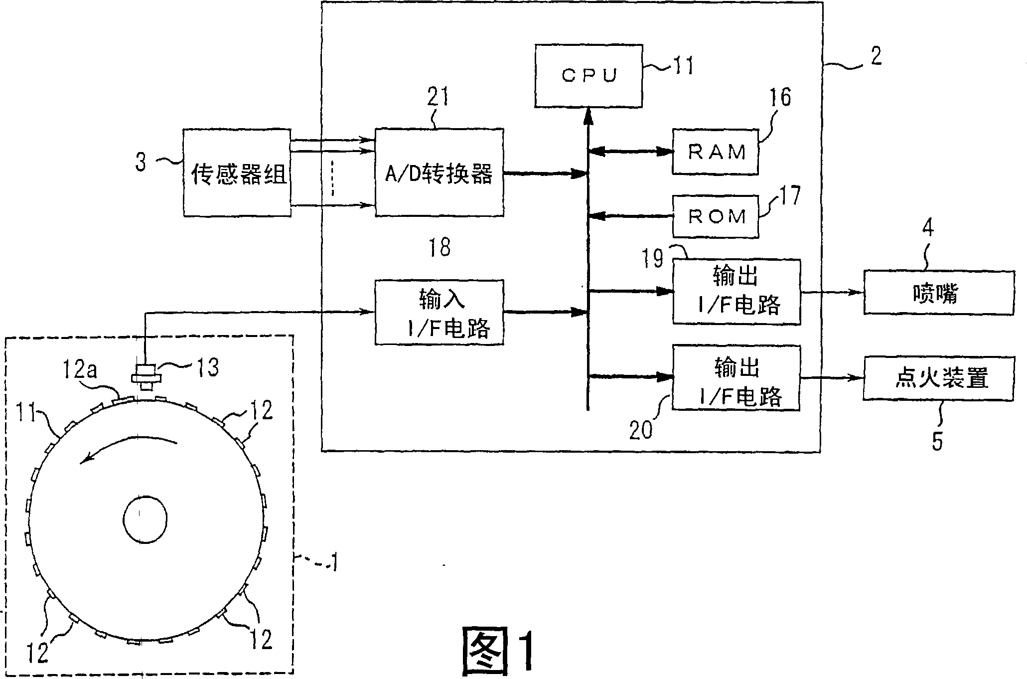
[0016] FIG. 1 shows an engine control device to which the crank angle detecting device of the present invention is applied. This engine control device includes: a crank angle detection device 1 , an ECU (Electric Control Unit: electronic control unit) 2 , a sensor group 3 , a nozzle 4 and an ignition device 5 .

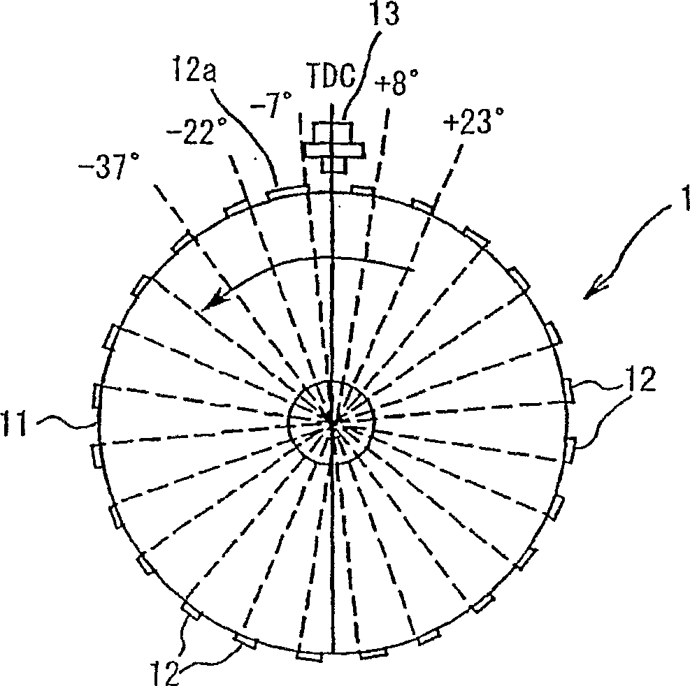
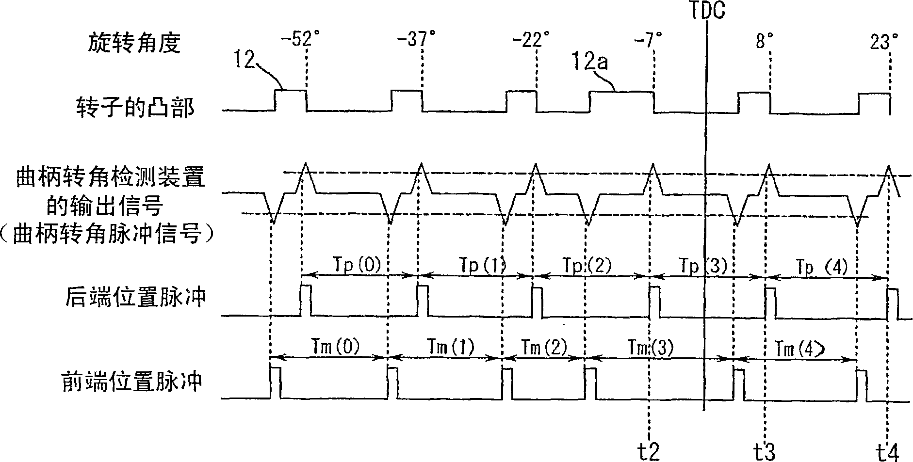
[0017] The crank angle detection device 1 includes a disc-shaped rotor 11 provided on a crankshaft (not shown) of a four-cycle internal combustion engine, and the rotor 11 rotates in conjunction with the rotation of the crankshaft. On the outer peripheral surface of the rotor 11, 24 protrusions 12 made of a magnetic material are continuously provided at intervals of 15 degrees as detected parts. An electromagnetic pickup (pickup) 13 is provided near the outer periphery of the rotor 11 . When the rotor 11 rotates, a pair of negative pulses and positi...


PUM


Abstract

The present invention provides a crank angle detection device and an ignition timing control device for an internal combustion engine. The crank angle detection device includes: a rotor that rotates in conjunction with a crankshaft of the internal combustion engine and has a plurality of detected parts at equal angular intervals on the outer periphery; The pick-up that generates a pulse signal each time the detected portion passes near the outer circumference of the rotor uses the detected portion located before the crank angle corresponding to the top dead center of the piston of the internal combustion engine among the plurality of detected portions for the crank Reference angle detection for corners.

Description

technical field [0001] The invention relates to a crank angle detection device and an ignition timing control device of an internal combustion engine. Background technique [0002] In the case of controlling the fuel injection timing for injecting and supplying fuel to the internal combustion engine through the nozzle or the ignition timing for spark discharge to the spark plug, the rotational angle position, that is, the crank angle is detected from the reference position of the crankshaft of the engine, and the crank angle is set based on the crank angle. set these timings. [0003] In a crank angle detection device for detecting the rotation angle of a crankshaft of an internal combustion engine, a disk-shaped rotor that rotates in accordance with the rotation of the crankshaft and an electromagnetic pickup provided near its outer periphery are used. Protrusions or recesses made of a plurality of magnetic materials are provided at every predetermined angle as detected po...

Claims


Application Information

Patent Timeline
Patent Type & Authority Applications(China)
IPC IPC(8): F02D35/00F02D45/00F02P5/15F02P7/067F02D41/34
CPCF02P5/15F02P7/0675F02D41/009F02P3/045Y02T10/46Y02T10/40
Inventor 铅隆司德川和人千田悟司
Owner KEIHIN CORP
Why Eureka
Try Eureka