Coiling apparatus of re-spooling machine

A technology of coiling device and rewinding machine, which is applied in the direction of transportation and packaging, conveying filamentous materials, thin material processing, etc. It can solve the problems of low efficiency and inability to accurately control the width adjustment value, so as to improve production efficiency and reduce The effect of operational difficulty

Active Publication Date: 2006-07-26
SUZHOU AOZHI INTELLIGENT EQUIP CO LTD
View PDF0 Cites 8 Cited by
  • Summary
  • Abstract
  • Description
  • Claims
  • Application Information

AI Technical Summary

Problems solved by technology

[0002] See attached Figure 9 - attached Figure 11 The existing rewinding machine coiling device includes a base, a first vertical arm and a second vertical arm fixedly arranged on the base, a first turntable rotatably arranged on the first vertical arm, and a first turntable rotatably arranged on the second vertical arm. The shaft sleeve on the two vertical arms, the screw sleeve arranged on the shaft sleeve, and the second turntable that is threadedly connected with the screw sleeve, a sliding shaft can be inserted in the shaft sleeve in an axially slidable manner, and the sliding shaft is provided with a The core for coiling the copper tube is equipped with an oil cylinder on the second vertical arm, and the sliding shaft is controlled by the piston rod of the oil cylinder to move, thereby driving the core to move, so that the core moves out of the second turntable and is between the first turntable and the second turntable. Between the two turntables, the shaft sleeve drives the sliding shaft and the barrel core to rotate, and the copper tube can be wound on the barrel core to form a coiled coil, and the width of the winding coil of the device is determined by the first turntable and the second turntable. The distance between them is controlled. The existing method of adjusting the distance is to manually rotate the second turntable, which is transformed into the axial displacement of the second turntable through the rotation of the second turntable relative to the screw sleeve, so that the first turntable can be adjusted. The distance between the second turntable and the second turntable, but this method of manually adjusting the distance between the second turntable and the first turntable is not only inefficient, but also cannot accurately control a reasonable width adjustment value. The movement of the second turntable will cause the second turntable to sag after being used for a period of time due to the wear between the shaft hole and the thread, which will directly affect the parallelism between the first turntable and the second turntable, thus affecting normal production

Method used


Image

  • Coiling apparatus of re-spooling machine
  • Coiling apparatus of re-spooling machine
  • Coiling apparatus of re-spooling machine

Examples


Embodiment Construction

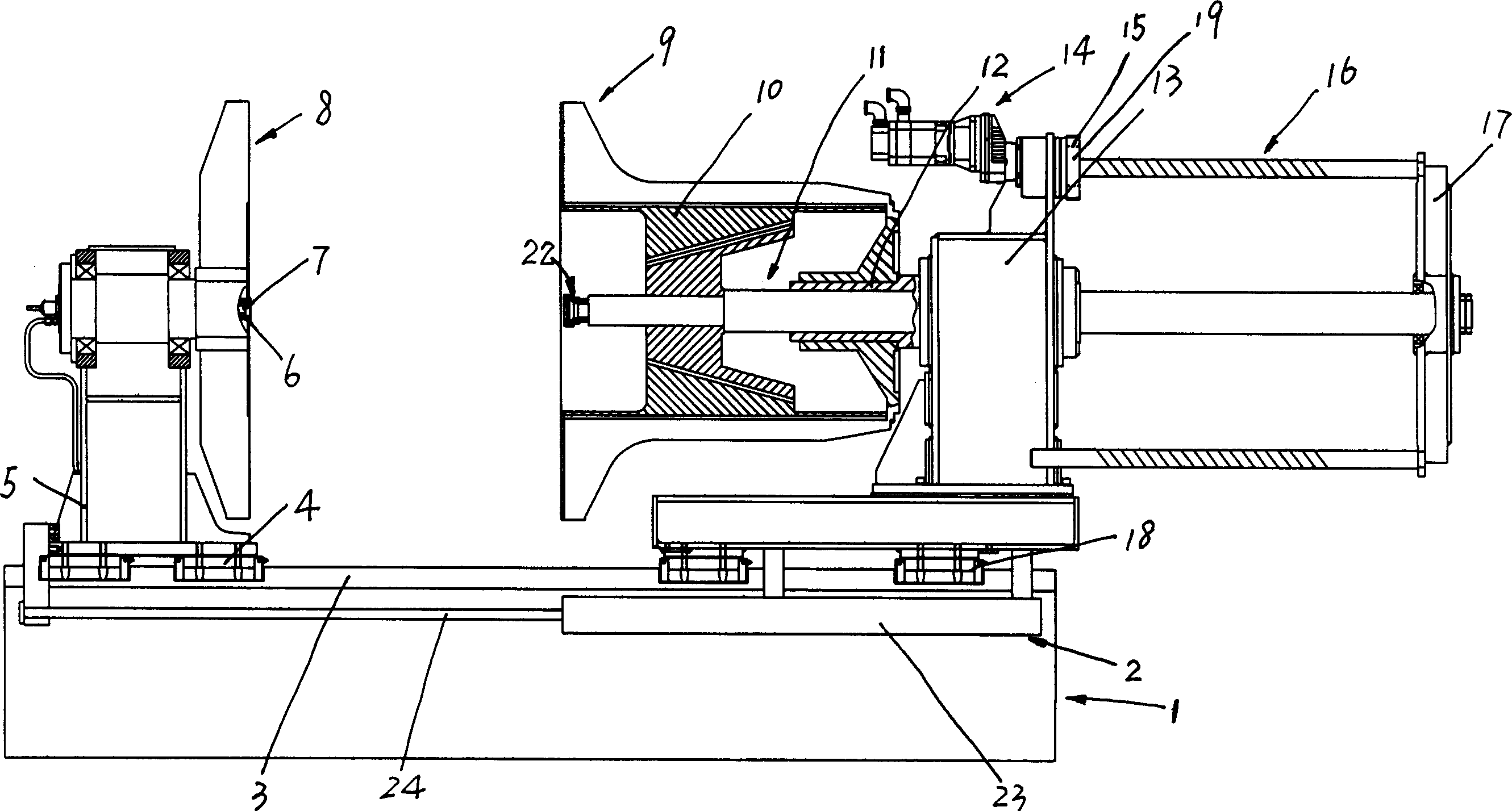
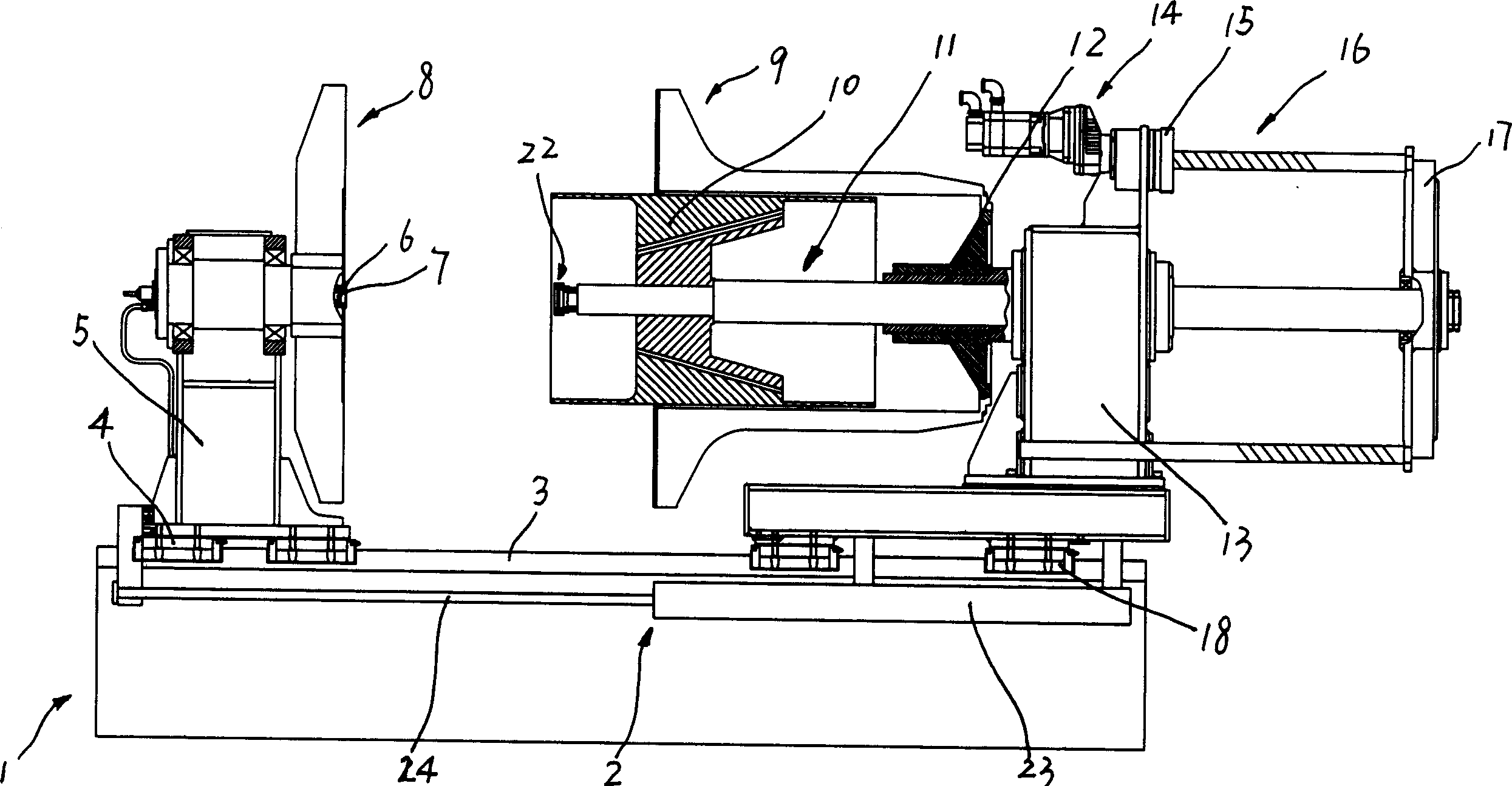
[0023] See attached figure 1 - attached Figure 8 , a winding device for a rewinding machine, which includes an underframe 1, a guide rail 3 arranged on the underframe 1, a first vertical arm 5 and a second vertical arm 13 slidably arranged on the guide rail 3, The first turntable 8 rotatably arranged on the first vertical arm 5, the second turntable 9 rotatably arranged on the second vertical arm 13, and the second turntable 9 rotatably arranged on the second vertical arm 13 The sliding shaft 11 on the top, the sliding shaft 11 is also slidably arranged relative to the second vertical arm 13 along the axial direction of the second turntable 9, and the sliding shaft 11 is locked relative to the second turntable 9, the second The vertical arm 13 is provided with a main shaft sleeve 12, the sliding shaft 11 is rotatably inserted in the main shaft sleeve 12, and the sliding shaft 11 and the main shaft sleeve 12 are relatively detented, and the second turntable 9 is fixedly arra...


PUM


Abstract

The invention relates the re-spooling machine batching apparatus, comprising the guide rail, the first vertical-boom and the second vertical-boom on guide rail, the first rotary table on the first vertical-boom, the second rotary table and sliding shaft on the second vertical-boom, and the barrel on sliding shaft. The part of barrel is between the first rotary table and the second rotary table when the barrel is under convolution status. The one end of sliding shaft is connected with the first rotary table; the other end of sliding shaft is connected with trail sleeve, the motor is installed on the second vertical-boom, the feed screw nut is connected with the output shaft of motor, the screw-thread in feed screw nut is matched with the guide screw, and the guide screw is connected with trail sleeve. The motor controls the movement distance of sliding shaft, and control the distance between the first rotary table and the second rotary table.

Description

technical field [0001] The invention relates to a winding device of a rewinding machine, which is used for tightly and orderly winding copper pipes into coiled pipes. Background technique [0002] See attached Figure 9 - attached Figure 11 The existing rewinding machine coiling device includes a base, a first vertical arm and a second vertical arm fixedly arranged on the base, a first turntable rotatably arranged on the first vertical arm, and a first turntable rotatably arranged on the second vertical arm. The shaft sleeve on the two vertical arms, the screw sleeve arranged on the shaft sleeve, and the second turntable that is threadedly connected with the screw sleeve, a sliding shaft can be inserted in the shaft sleeve in an axially slidable manner, and the sliding shaft is provided with a The core for coiling the copper tube is equipped with an oil cylinder on the second vertical arm, and the sliding shaft is controlled by the piston rod of t...

Claims


Application Information

Patent Timeline
IPC IPC(8): B65H54/02B65H54/54B65H54/40B65H79/00
Inventor 闫瑞凌雪刚
Owner SUZHOU AOZHI INTELLIGENT EQUIP CO LTD
Why Eureka
Try Eureka