
Disk birotor dual veer DC brushless motor

A DC brushless, dual-steering technology, applied in the field of electric motors, can solve the problems of wasting electric energy, small torque, large energy consumption, etc., and achieve the effect of expanding the scope of promotion and use, reducing manufacturing difficulty, and continuous and stable operation.

Inactive Publication Date: 2011-02-23
曾琼东
View PDF0 Cites 0 Cited by
  • Summary
  • Abstract
  • Description
  • Claims
  • Application Information

AI Technical Summary

Problems solved by technology

Traditional DC motors usually use brushes to commutate mechanically, but this method has defects such as severe mechanical friction, large noise and sparks, and short life. At the same time, high manufacturing costs and difficult maintenance make its development and use subject to limit
For this reason, DC brushless motors have developed rapidly in recent years. It uses a brushless electronic commutator for commutation. Although this method has many advantages such as reliable operation of AC motors and good speed regulation performance, it is simple and convenient. Direct current cannot work, it must pass through an electronic commutator to run, but the cost of the electronic commutator is too high
In addition, the brushless DC motor currently used has many components, usually consisting of the motor body (including the main stator and the main rotor), the electronic switch circuit (including the power logic switch and position signal processing) and the position sensor (including the sensor stator and the sensor rotor) ) structure, there are also defects such as high manufacturing cost, difficult assembly and maintenance, etc., thus limiting the application range of DC brushless motors
[0003] In addition, most of the rotors of existing motors are cylindrical, and the force on the rotor acts on the outer surface of the cylinder, and the torque it receives is small, so the torque is also small and the energy consumption is large
At the same time, the cutting between the stator coil and the magnetic force line changes, and the magnetic flux on the stator coil will also change, so the counter electromotive force will be induced. To overcome the counter electromotive force, the starting current is several times the rated current, wasting a lot of electric energy. , also affects device performance and operation

Method used


Image

  • Disk birotor dual veer DC brushless motor
  • Disk birotor dual veer DC brushless motor
  • Disk birotor dual veer DC brushless motor

Examples


Embodiment Construction

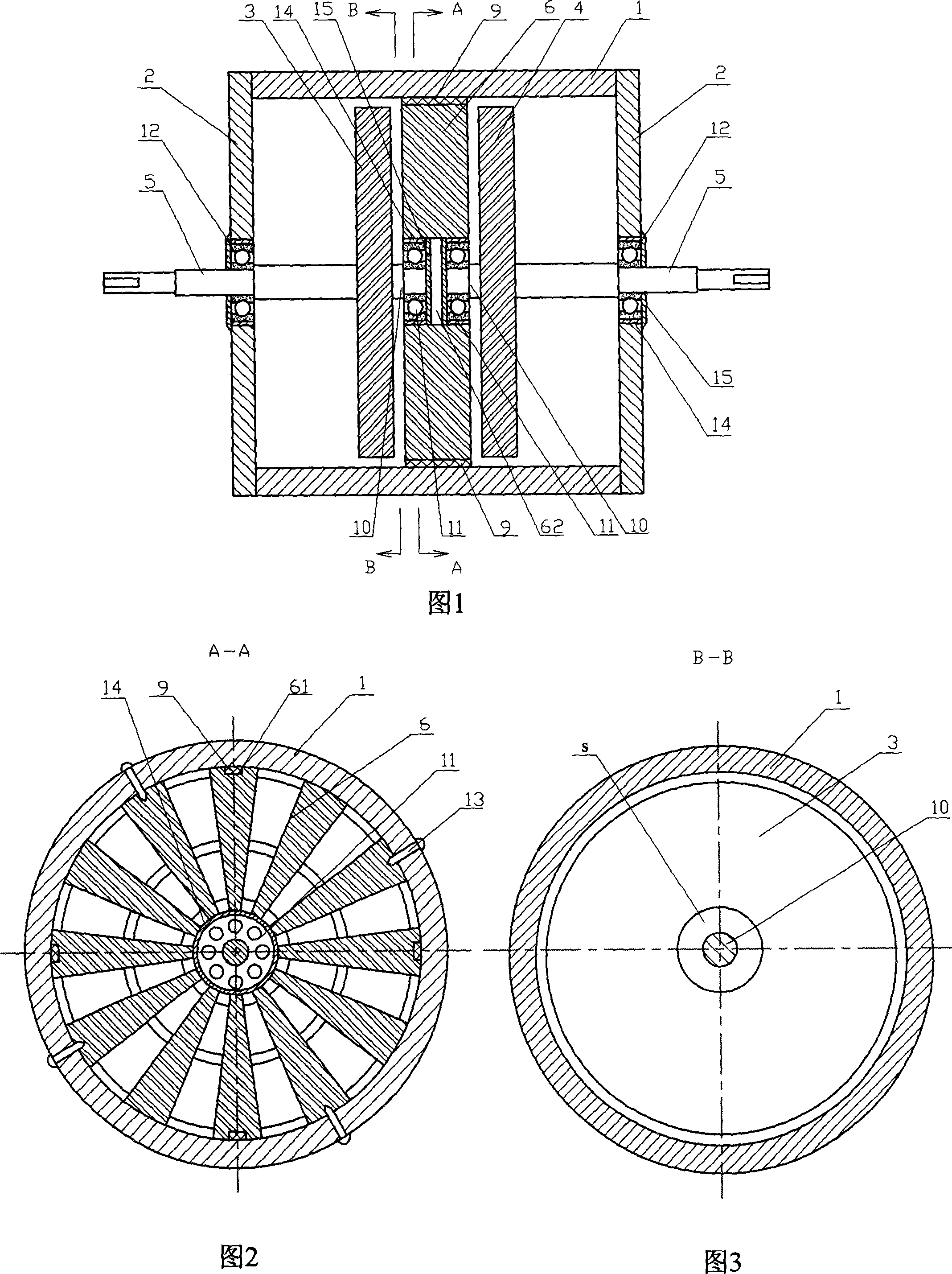
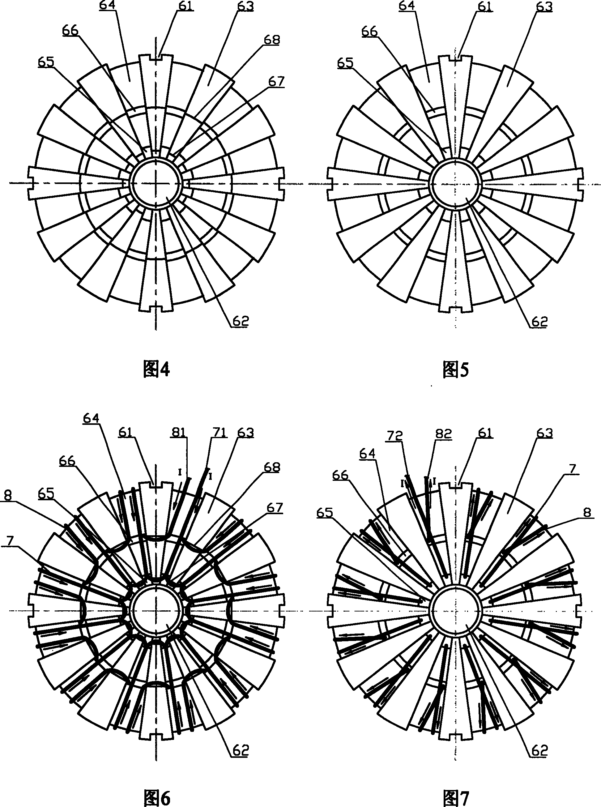
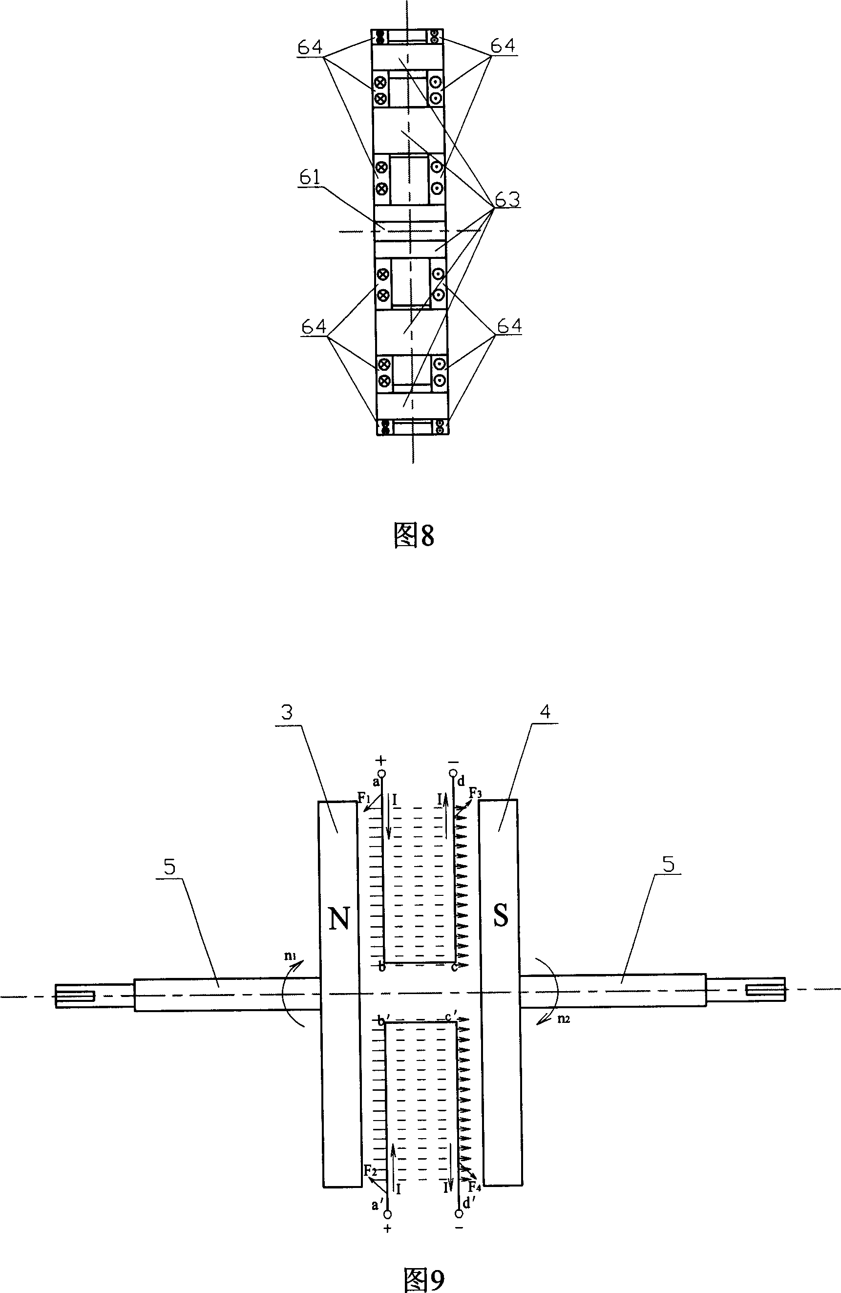
[0029] Figure 1 to Figure 9 Shown is an embodiment of the present invention, including a frame 1, an end cover 2, a stator, rotors 3 and 4, an output shaft 5, and the stator includes a stator core 6 and a stator winding. Such as figure 1 As shown, the end cover 2 is arranged at both ends of the frame 1, and the stator core 6 and the rotors 3 and 4 are all disc-shaped (see figure 2 with image 3 ), wherein the rotors are two permanent magnets, namely the N-pole rotor 3 and the S-pole rotor 4. In order to avoid the magnetic force between the rotor and the machine base and the end cover, the two rotors can also have N poles and S poles on the inner side only. The two rotors are vertically arranged in the machine base 1 respectively, and the inner surfaces thereof are corresponding to each other. One stator core 6 is vertically fixed between the two rotors, and its left and right sides correspond to the inner surfaces of the two rotors respectively. Such as figure 1 with ...


PUM


Abstract

The invention discloses a disc dual-rotor dual-rotation direction dc brushless motor, which comprises: a base, an end cap on two ends of base, a stator with a disc stator core fixed between rotors and a disc stator winding sector-shaped coiled on core, two rotors with inner surface as N and S-pole permanent magnets and arranged vertically in base, and output shaft with one end fixed on outer surface of rotor ad another end extended out the cap. Wherein, the two side surfaces of stator core are opposite to the inner surfaces of rotor; the stator core has same current direction as winding coil on same side while the current direction of two windings opposite. This invention has simple structure, runs reliably, and can reduce cost and energy consumption.

Description

technical field [0001] The invention relates to a motor, in particular to a DC brushless motor. Background technique [0002] The DC motors currently used all need a reversing device to maintain the continuous operation of the rotor. Traditional DC motors usually use brushes to commutate mechanically, but this method has defects such as severe mechanical friction, large noise and sparks, and short life. At the same time, high manufacturing costs and difficult maintenance make its development and use subject to limit. For this reason, DC brushless motors have developed rapidly in recent years. It uses a brushless electronic commutator for commutation. Although this method has many advantages such as reliable operation of AC motors and good speed regulation performance, it is simple and convenient. Direct current cannot work and must be operated through an electronic commutator, but the cost of the electronic commutator is too high. In addition, the brushless DC motor curre...

Claims


Application Information

Patent Timeline
Patent Type & Authority Patents(China)
IPC IPC(8): H02K16/02H02K1/27H02K57/00
Inventor 曾琼东
Owner 曾琼东
Learn More