
Press cylinder

A printing cylinder and cylinder technology, applied in printing, printing machines, rotary printing machines, etc., can solve the problems of unguaranteed reliability of folding claws or pin rods, unfavorable printing cylinders, and the influence of slip rings, etc.

Inactive Publication Date: 2006-06-21
M A N ROLAND DRUCKMASCHINEN AG
View PDF0 Cites 0 Cited by
  • Summary
  • Abstract
  • Description
  • Claims
  • Application Information

AI Technical Summary

Problems solved by technology

However, the disadvantage of introducing current into the rotating printing cylinder through the slip ring is that the slip ring is easily affected, so the reliability of the folding claws or pins is not guaranteed
Therefore, in general, it is disadvantageous to introduce current into the rotating printing cylinder through slip rings

Method used


Image

  • Press cylinder

Examples


Embodiment Construction

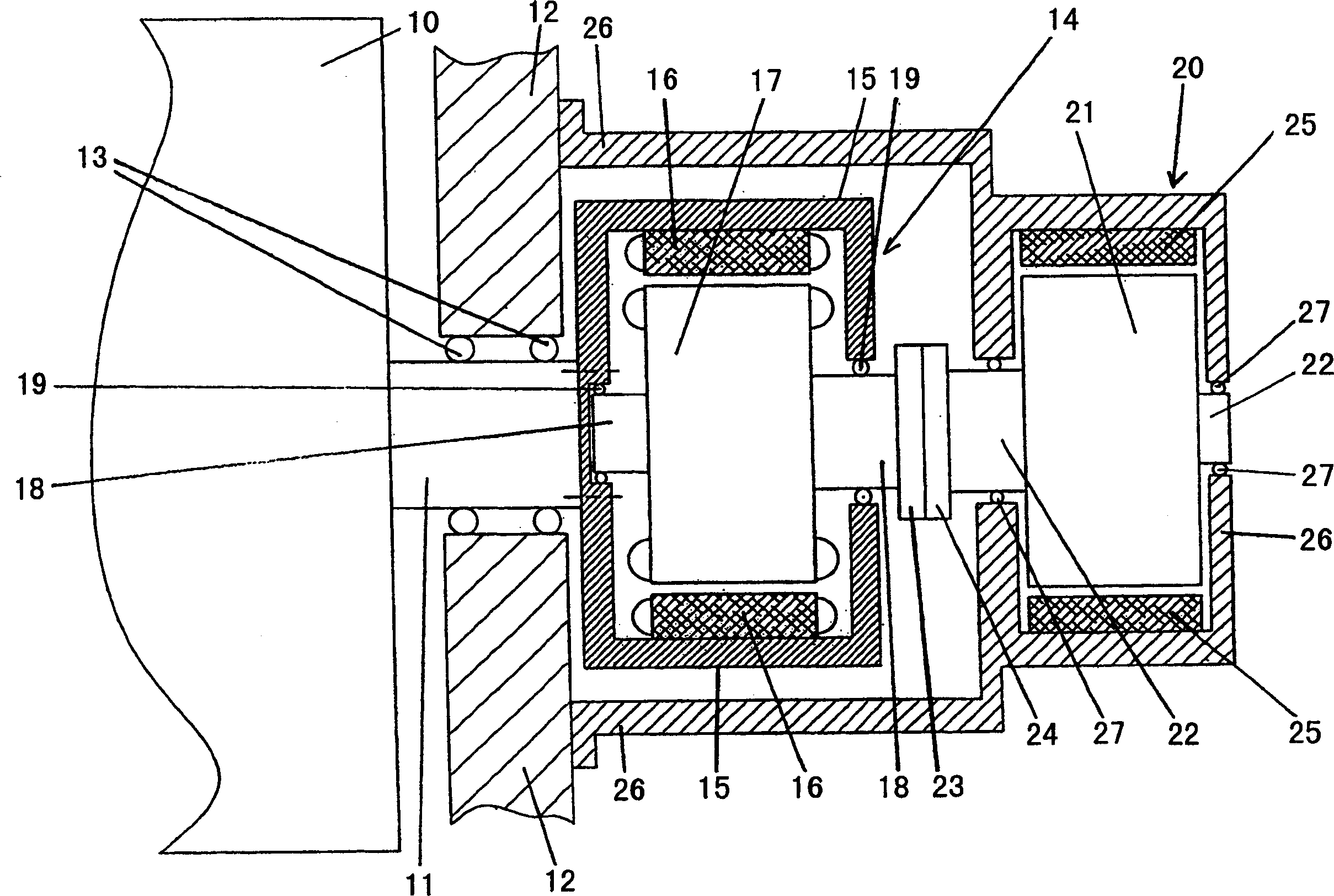
[0011] In the text below, reference will be made to figure 1 The present invention will be described in detail. figure 1 A detail of a printing cylinder 10 is shown, the shaft 11 of which is mounted on a fixed frame 12 . The printing cylinder 10 and its shaft 11 rotate relative to a fixed frame 12 in which a bearing 13 for mounting the shaft 11 of the printing cylinder 10 is mounted.

[0012] At least one drivable device, not shown in the figures, is accommodated in the printing cylinder 10 . If the printing cylinder 10 is designed as a folding claw cylinder of a printing folding unit, a plurality of driveable devices designed as folding claws are integrated in the printing cylinder. On the other hand, if the printing cylinder 10 is designed as a pin cylinder of a printing and folding unit, the driveable means integrated in the printing cylinder are the pins and the folding flaps. On the other hand, if the printing cylinder 10 is designed as a forme cylinder, the drivable d...


PUM


Abstract

The invention relates to a printing cylinder (10) having at least one drivable means and a generator (14) assigned to the printing cylinder (10) for generating electrical energy to actuate the or each drivable means. According to the invention, the generator housing (15) of the generator (14) is permanently connected to and rotates with the printing cylinder (10), belonging to the generator (14) and enclosed by the generator housing (15) The generator rotor (17) rotates relative to the generator housing (15), and the generator rotor (17) can be driven by an electric motor (20).

Description

technical field [0001] The present invention relates to a printing cylinder according to the preamble of technical solution 1 . Background technique [0002] Printing presses have a plurality of cylinders in which devices that can be driven or operated electrically are integrated. Examples that may be mentioned here are the folding jaw cylinders of the printing folding unit, in which folding jaws that can be driven or operated electrically are integrated. Another example is the plate cylinder of a printing unit of a printing press, in which it is possible to integrate an electrically driven or electrically operated clamping device of the printing plate. [0003] To drive or operate the devices integrated in the printing cylinders, electrical energy or current is required, which is generated by generators assigned to the individual printing cylinders. According to the prior art, in order to be able to operate the drivable device with the current introduced in this way, the ...

Claims


Application Information

Patent Timeline
Patent Type & Authority Applications(China)
IPC IPC(8): B41F13/08B41F13/004B41F13/20
CPCB41F13/0045B41F13/62B41F27/005B41P2213/126B65H45/162H02K7/1807H02K16/005
Inventor P·迈尔
Owner M A N ROLAND DRUCKMASCHINEN AG
Learn More