Tool for formed metal plate and section bar

A metal plate and tool technology, applied in the field of forming metal plates and profiles, can solve the problems of increased sensitivity to jaw wear, high machining costs, and complex assembly

Active Publication Date: 2006-05-03
JAGAO
View PDF1 Cites 3 Cited by
  • Summary
  • Abstract
  • Description
  • Claims
  • Application Information

AI Technical Summary

Problems solved by technology

[0003] The disadvantage of this example is that the machining of such tool parts with grooves and

Method used


Image

  • Tool for formed metal plate and section bar
  • Tool for formed metal plate and section bar

Examples


Embodiment Construction

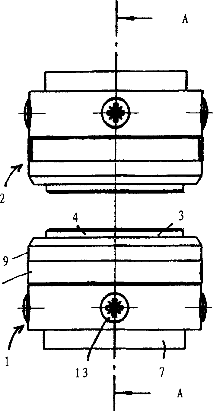
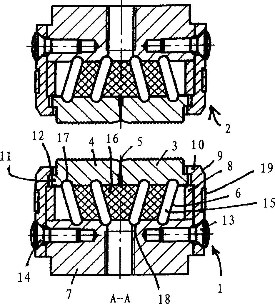
[0012] figure 1 and figure 2 The tool shown comprises a lower tool part 1 and an upper tool part 2 which are of identical construction and which interact to shape the material clamped in place therebetween. In this example, the respective structures of the tool lower part 1 and the tool upper part 2 are as follows.

[0013] A pair of jaws 3, 4 comprises two semi-cylindrical jaws which together form a parting line 5 and are movable in opposite directions for upsetting, spreading or drawing motions . The jaws 3 , 4 are arranged centrally on a deformable support element 6 . This support element 6 is in turn supported on a support element 7 which rests on an actual support base (not shown in the figure). In an edge region, the clamping jaws 3 , 4 rest on an anti-shock ring 8 , which surrounds the support element 6 and is in turn supported on the support element 7 . The individual parts inserted one inside the other and placed one on the other are fixed together by means of a...


PUM


Abstract

A tool for forging, exhibition forging, and pulling metal boards and profiles, with two clamps that are clamped between them between them and can move in the opposite direction, in order to achieve 镦 Forging, exhibition exhibitions, exhibitionsForging or pulling exercise.The clamps on the same side of the metal board are supported on the support element via a deformable support element, forming a sub -module and fixing through the sleeve.The radial extension part, the radial extension part is placed on the anti -impact ring of the circle bridge connection support element between the support element and the claw claw, and the sleeve with a closed edge is placed on the surrounding clamp. The closed edge and anti -resistanceThe impact ring forms a sliding guidance department, so that the clamping clamp is set in the sleeve in a gap along the radial band.

Description

technical field [0001] The invention relates to a tool for forming sheet metal and profiles, in particular for upsetting, expanding and drawing sheet metal and profiles. Background technique [0002] Such a tool is disclosed in German Patent DE 1093311, which comprises two pairs of jaws which clamp the material in place between them and which are relatively movable in order to perform an upsetting or spreading movement. In this example, the jaws are placed on deformable support elements, which are in turn supported on the lower part. Those separate parts which are inserted one into the other and placed one on top of the other are held together by means of a two-piece sleeve whose flanges engage in grooves in the jaws and the lower part. These sleeve halves are fastened together with countersunk screws. [0003] A disadvantage of this example is that the machining of such a tool part with grooves and edges is expensive due to the complex assembly and the increased susceptib...

Claims


Application Information

Patent Timeline
IPC IPC(8): B21K27/00B21C1/28B21D11/08
CPCB21D11/085
Inventor 汉斯-于尔根·伦纳
Owner JAGAO
Why Eureka
Try Eureka