Supporting rack

A technology of supporting frame and supporting components, which is applied in the direction of electrical components, semiconductor/solid-state device manufacturing, circuits, etc., can solve the problems of poor supporting optical axis transmission pipelines, etc., achieve good fixing effect, and reduce the chance of overlapping pipelines , easy to obtain effect

Inactive Publication Date: 2006-04-26
POWERCHIP SEMICON CORP
View PDF0 Cites 0 Cited by
  • Summary
  • Abstract
  • Description
  • Claims
  • Application Information

AI Technical Summary

Problems solved by technology

[0005] Therefore, the main purpose of the present invention is to provide a support frame for supporting the optical axis transmission pipeline between the light source generator of the exposure machine and the host machine, so as to solve the poor effect of the above-mentioned traditional technology on supporting the optical axis transmission pipeline. The problem

Method used


Image

  • Supporting rack
  • Supporting rack
  • Supporting rack

Examples


Embodiment Construction

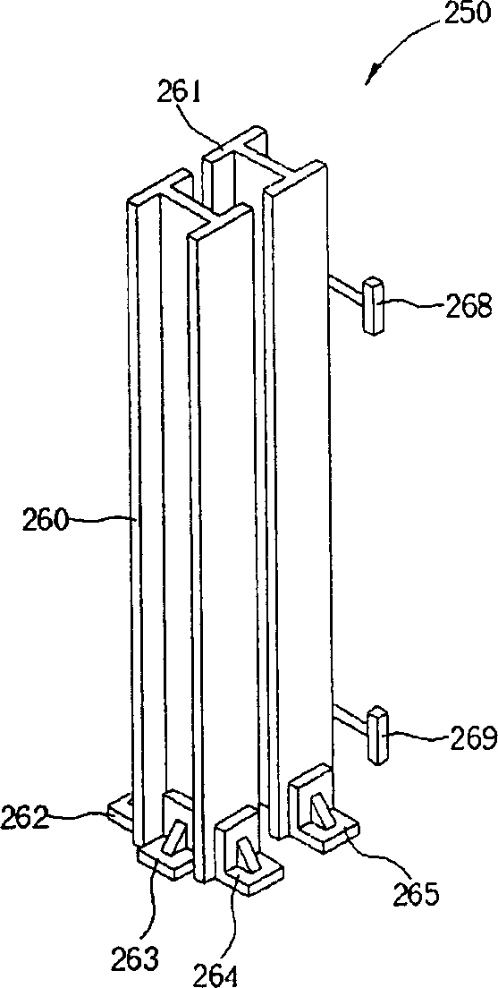
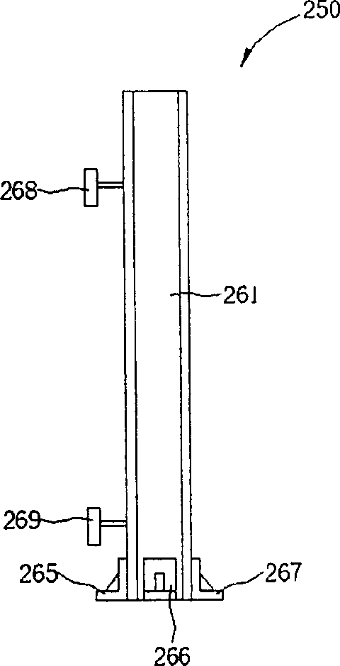
[0016] Please refer to figure 2 , image 3 and Figure 4 , figure 2 is a three-dimensional schematic diagram of the support frame 250 of the present invention, image 3 for figure 2 A side view of the support frame 250 is shown, Figure 4 It is a schematic diagram of the application of the support frame 250 of the present invention. Such as figure 2 with image 3 As shown, the supporting frame 250 includes a plurality of H-shaped steels 260, 261 arranged in parallel and supporting components 262-267, wherein the supporting components 262-267 are used to make the H-shaped steels 260, 261 fixedly engaged with the floor, and support the H-shaped steels 260, 261, for example, if Figure 4 As shown, one end of the plurality of supporting components 262-264 is set on the first part of the H-shaped steel 260, such as the bottom end, and the other end is set on the floor of the floor 230, so that the H-shaped steel 260 and the floor 230 can be fixed well. Engages and effe...


PUM


Abstract

The invention discloses a support rack, which comprises the following parts: at least one light source generator on the exposure machine, H-beam between host computer and working bench; light axis transportation pipeline to support exposure machine, at least one support component on the first position of H-beam, signal launcher on the second position of H-beam and signal receiver on the third position of H-beam to detect the deviation phenomenon of light axis.

Description

technical field [0001] The invention provides a supporting object, in particular a supporting frame for supporting the optical axis transmission pipeline of an exposure machine. Background technique [0002] Most of the high-energy exposure machines currently used in fabs are placed separately from auxiliary machines such as light source generators and host machines such as steppers and scanners to avoid the need for staff or hosts to work The machine is affected by the high temperature, particles, noise, vibration and high-energy radiation generated by the light source generator, causing damage, and because the host machine must be placed in a clean room to avoid Contaminate particles to ensure the yield rate of the process. However, the construction cost of the clean room is expensive. Therefore, most of the current planning methods are to place the light source generator of the exposure machine and the main machine working table separately on different floors to save more...

Claims


Application Information

Patent Timeline
IPC IPC(8): G03F7/20H01L21/00
Inventor 陈茂森王宏祺郭宗铭
Owner POWERCHIP SEMICON CORP
Why Eureka
Try Eureka