
Image forming apparatus and a paper feeding apparatus for the same

一种成像装置、辊子的技术,应用在应用电荷图形的电记录工艺、应用电荷图形的电记录工艺的设备、运输和包装等方向,能够解决增加生产成本、增加部件数量、增加装置尺寸等问题,达到操作均匀的效果

Inactive Publication Date: 2006-04-12
SAMSUNG ELECTRONICS CO LTD
View PDF0 Cites 4 Cited by
  • Summary
  • Abstract
  • Description
  • Claims
  • Application Information

AI Technical Summary

Problems solved by technology

Thus, increasing the size of the entire device
Also, the dedicated paper feed roller 13 increases the number of parts in the device, thus increasing the production cost

Method used


Image

  • Image forming apparatus and a paper feeding apparatus for the same
  • Image forming apparatus and a paper feeding apparatus for the same
  • Image forming apparatus and a paper feeding apparatus for the same

Examples


Embodiment Construction

[0037] Matters defined in the description, such as detailed structure and elements, are helpful for a comprehensive understanding of the embodiments of the present invention. Accordingly, those of ordinary skill in the art will recognize that various changes and modifications of the embodiments described herein can be made without departing from the scope and spirit of the invention. Also, descriptions of well-known functions and constructions are omitted for clarity and conciseness.

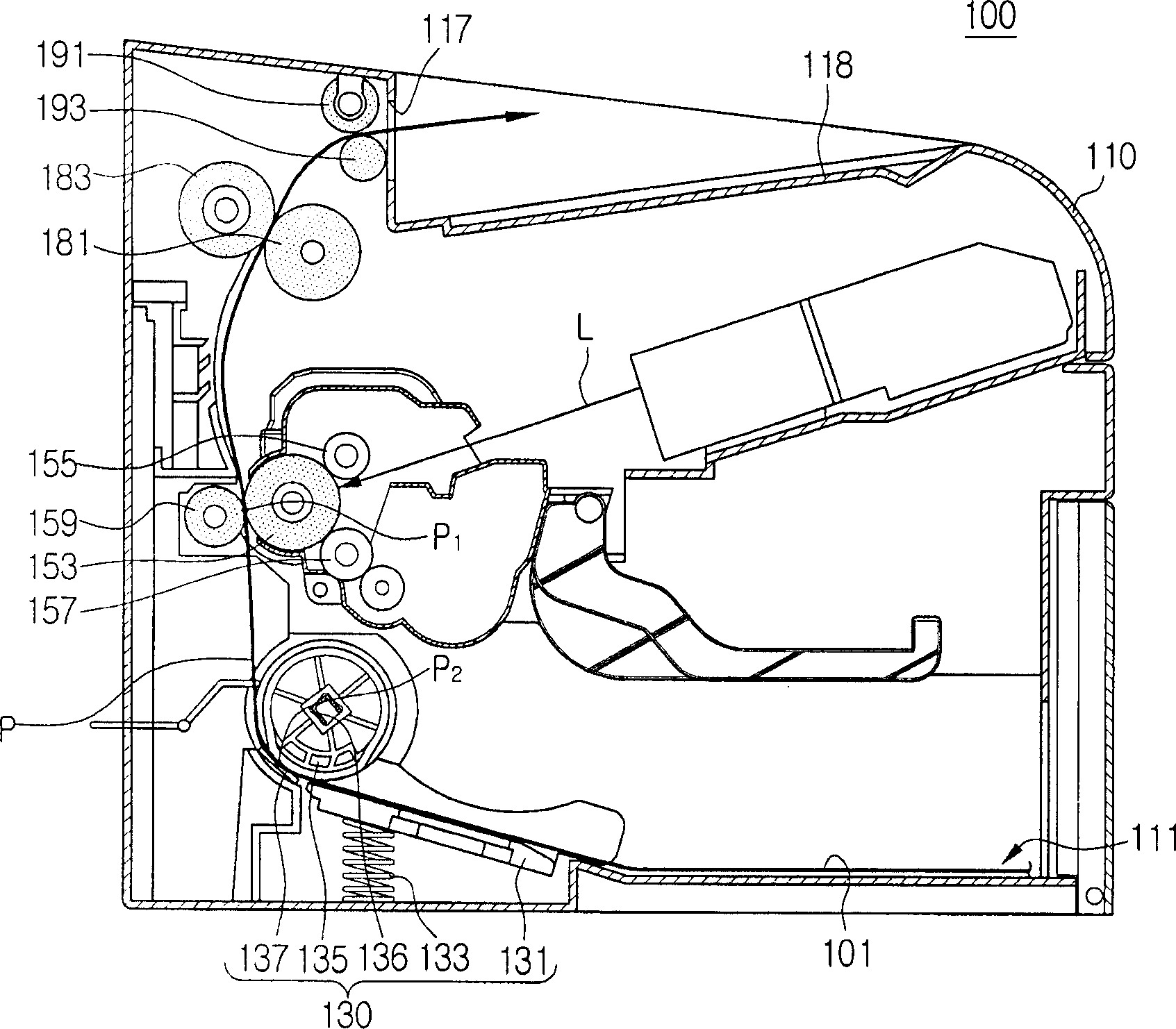
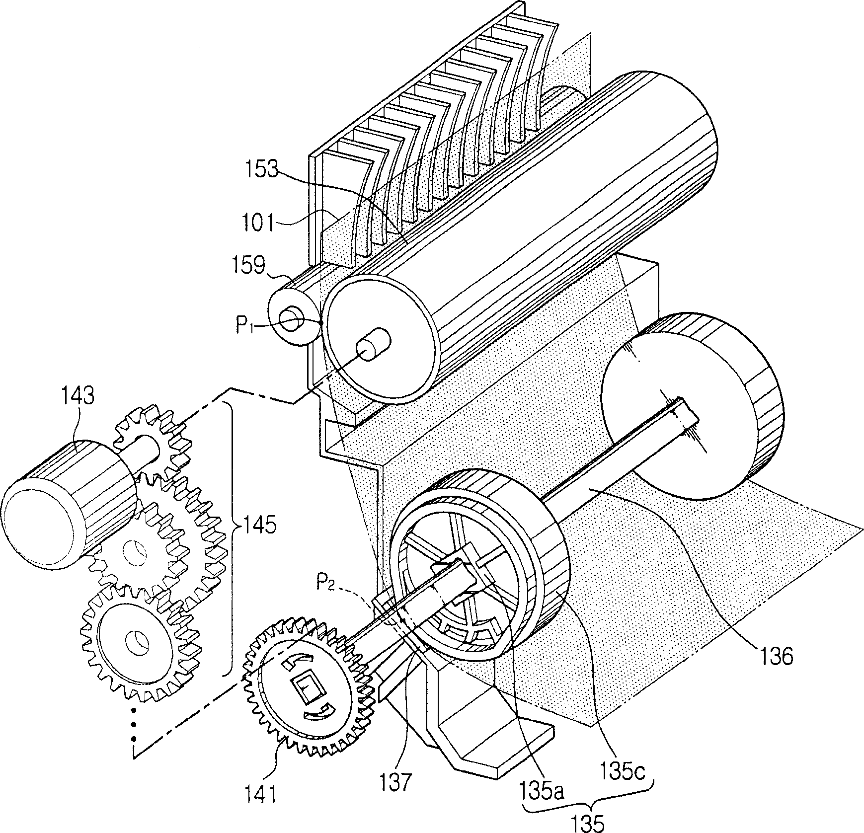
[0038] Refer to attached figure 2 , the paper feeding part 111 is formed on the inner surface of the bottom of the main body 110 . A knockup plate 131 for stacking a plurality of sheets of paper thereon is provided at the paper feeding section 111 . The biasing element 133 is located between the strike plate 131 and the main body 110 . Since the pickup roller 135 is rotated, the paper 101 stacked on the impact plate 131 is picked up one by one by the friction generated by the friction pad 13...


PUM


Abstract

An image forming apparatus feeds a paper picked up by a pickup roller directly to a photoconductive drum and controls a linear velocity of the pickup roller so that it is slower than that of the photoconductive drum. The different linear velocities of the pickup roller and the photoconductive drum produces different velocities at the transfer nip (the area of contact between the photoconductive drum and a transferring roller) and the point where paper is picked up by the pickup roller. To compensate for the different velocities, the pickup roller can be rotated faster than the photoconductive drum for an angle that corresponds to the velocity difference. Additionally, when a velocity difference occurs between two rollers for feeding the paper, one of the rollers can be further rotated to compensate for the velocity difference.

Description

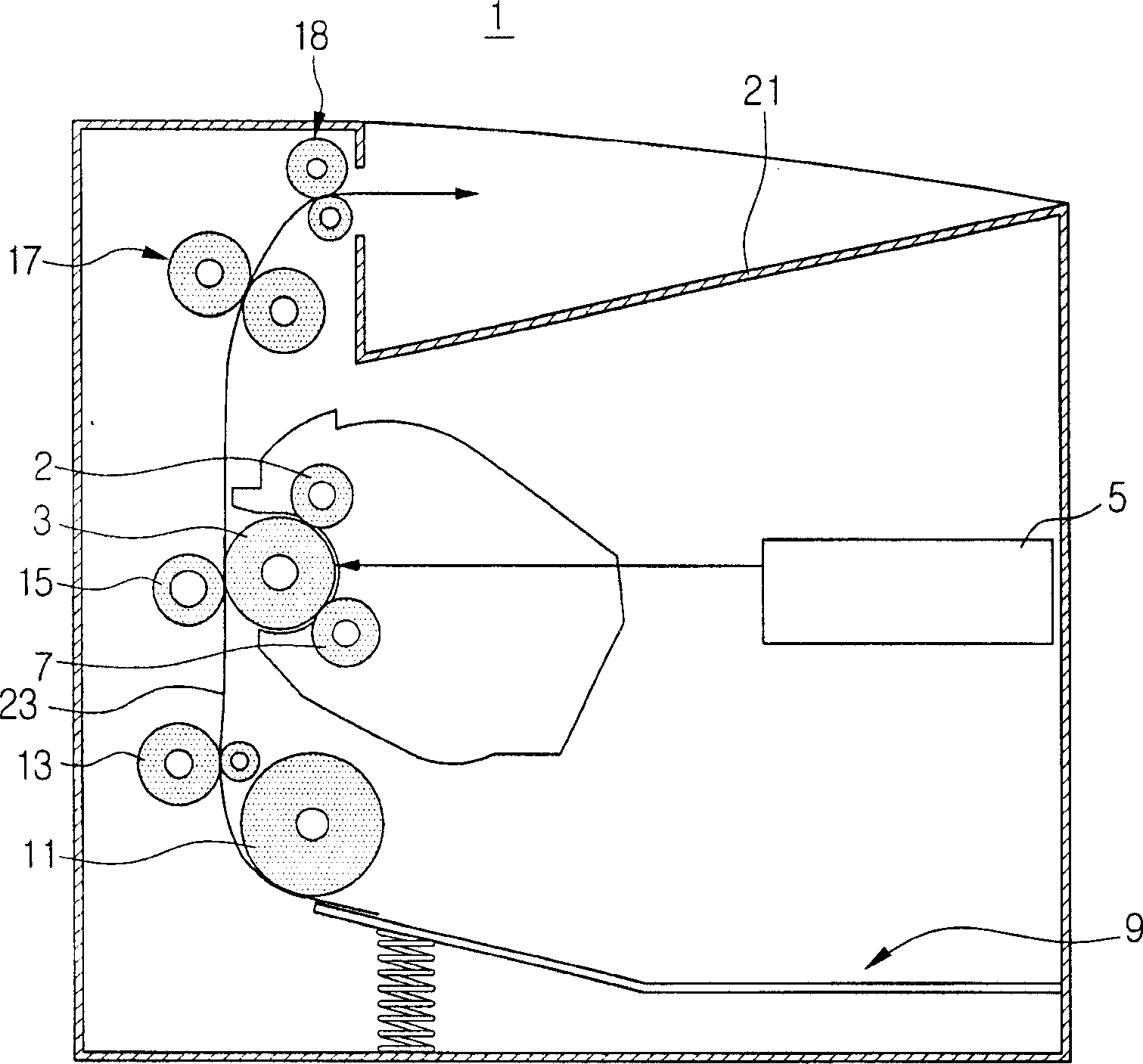
technical field [0001] The invention relates to an image forming device and a paper feeding device used in the image forming device. More particularly, the present invention relates to a paper feeding mechanism of an image forming apparatus capable of compensating for a speed difference of paper feeding rollers. Background technique [0002] Generally, in an electrophotographic image forming apparatus such as a laser printer, an electrostatic latent image is formed on a photosensitive medium (such as a photosensitive belt or a drum), and the electrostatic latent image is developed and transferred to paper using a developer of a certain color, thus producing desired image. [0003] figure 1 The printing process of the conventional image forming apparatus 1 is schematically shown. refer to figure 1 , the surface of the photosensitive drum 3 is uniformly charged by the charging roller 2 . The photosensitive drum 3 is exposed to a laser beam generated by a laser scanning un...

Claims


Application Information

Patent Timeline
Patent Type & Authority Applications(China)
IPC IPC(8): G03G15/00G03G15/14B65H5/06
CPCG03G15/6511G03G2215/00396B65H3/0638B65H3/5261G03G15/5008G03G15/5054G03G15/6558
Inventor 金贤镐卢周焕
Owner SAMSUNG ELECTRONICS CO LTD
Learn More