
Imaging device

A technology of camera equipment and camera department, which is applied in photography, image communication, wide-screen photography, etc., and can solve the problems such as the difficulty of using the mirror tapered mirror, the overall enlargement of the camera equipment, and the difficulty of all-round photography.

Inactive Publication Date: 2006-03-08
SONY GRP CORP
View PDF2 Cites 20 Cited by
  • Summary
  • Abstract
  • Description
  • Claims
  • Application Information

AI Technical Summary

Problems solved by technology

[0010] However, since the conical mirror must be provided, the overall size of the imaging device becomes larger, and it is difficult to use the conical mirror to prevent the mirror from being damaged or dirty.
[0011] Furthermore, due to the structure of the conical mirror, it is impossible to take pictures in the direction along the central axis of the cone (up and down in the layout of the usual conical mirror), so it is difficult to take all-round photography.

Method used


Image

  • Imaging device
  • Imaging device
  • Imaging device

Examples


Embodiment Construction

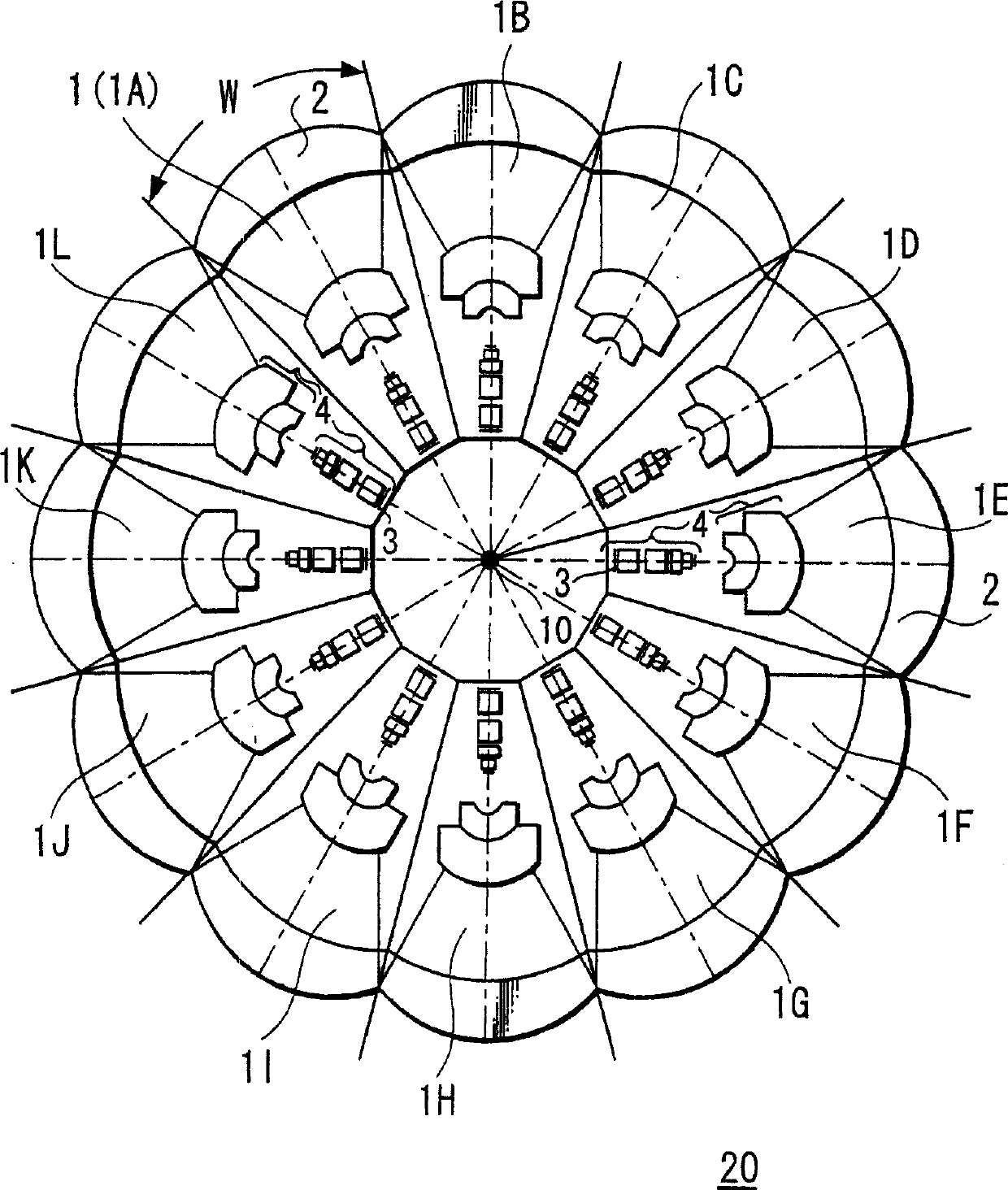
[0024] As one embodiment of the present invention, a schematic configuration diagram (cross-sectional view in the horizontal direction) of an imaging device is shown in FIG. 1 .

[0025] The image pickup device 20 has 12 (1A, 1B, 1C, 1D, 1E, 1F, 1G, 1H, 1I, 1J, 1K, 1L) image pickup units (cameras) equipped with a lens front lens 2 and an image pickup element 3. 1 in a radial layout, and adjacent imaging units 1 are joined to each other.

[0026] In each imaging unit 1 , a lens front lens 2 is provided at the front end thereof, and an imaging device 3 is provided near the rear end thereof, and a lens group 4 is provided between the lens front lens 2 and the imaging device 3 .

[0027] With such a configuration, in the horizontal direction, each of the imaging units 1A-1L is in charge of an imaging area of ​​30 degrees, for a total of 360 degrees of imaging area.

[0028] In addition, in order to superimpose the images captured by adjacent imaging units 1 and absorb mechanical ...


PUM


Abstract

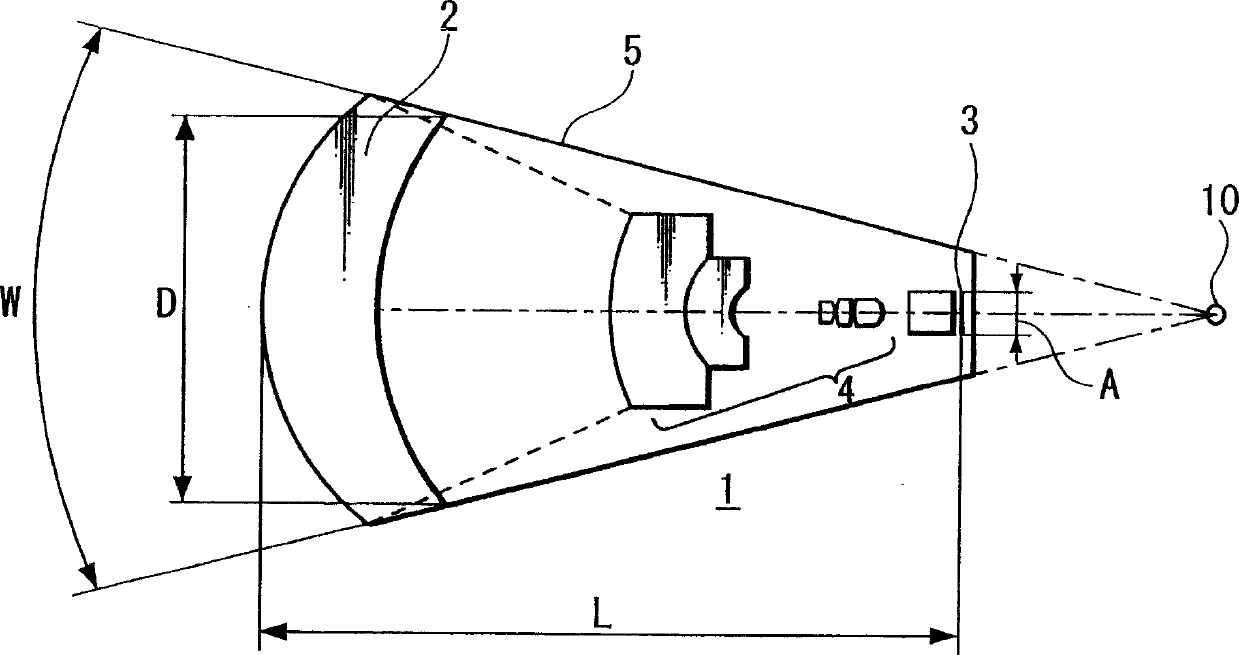
An imaging device capable of picking up a wide range from a plurality of imaging units, providing a good image quality, and being downsized. The imaging device (20) comprises a plurality of imaging units (1) each provided with an imaging element (3) and a lens front cell (2), wherein adjacent imaging units (1) are so disposed as to allow their imaging areas to be overlapped, and, when a section passing through a view point center, an imaging element (3), and a lens front cell (2) in this overlapping direction is assumed, a conditional expression, AL < fD (1), is satisfied and the view point center of each imaging unit (1) is disposed within a 20-mm sphere; where the section length of the imaging element (3) is A, the section length of the lens front cell (2) D, the distance from the lens front cell (2) to the imaging element (3) L, a focal distance obtained by combining the entire lens in the imaging unit (1) including the lens front cell (2) f.

Description

technical field [0001] The present invention relates to an image pickup device capable of taking pictures of a wide range such as a full circumference, having a plurality of image pickup units including lenses and image pickup elements. Background technique [0002] So far, many proposals have been made for an imaging device capable of simultaneously capturing images of a large viewing angle by using a plurality of cameras. [0003] For example, an imaging device in which a plurality of cameras are mounted on a polyhedral frame has been proposed (for example, refer to Patent Document 1). [0004] However, in this structure, since the centers of viewpoints of the respective cameras are inconsistent, parallax occurs between the respective cameras, and a plurality of images cannot be spliced ​​and synthesized with high quality. In addition, when you want to shoot a subject that is relatively close to the camera (extremely close-up), there will be a blind spot where you cannot ...

Claims


Application Information

Patent Timeline
Patent Type & Authority Applications(China)
IPC IPC(8): G03B37/04G03B15/00H04N5/225G02B13/06
CPCG03B37/04H04N5/2254G02B13/06G03B15/00H04N23/698H04N23/00H04N13/243
Inventor 吉川功一
Owner SONY GRP CORP
Learn More