
Device for remote monitoring and controlling power distribution

A power distribution device and remote monitoring technology, applied in the direction of circuit devices, electrical components, etc., can solve the problems of low equipment maintenance level, inability to accurately and timely grasp the operation status of power distribution equipment, difficult management of power distribution equipment, etc.

Inactive Publication Date: 2006-02-01
赵勤彪
View PDF0 Cites 4 Cited by
  • Summary
  • Abstract
  • Description
  • Claims
  • Application Information

AI Technical Summary

Problems solved by technology

[0002] In the existing technology, the power distribution equipment used by enterprises is regularly maintained and inspected by professionals. Once the power distribution equipment breaks down, it takes a long time for the maintenance personnel to find the fault and repair it; There is no automatic monitoring device on the power distribution equipment, so it is impossible to accurately and timely grasp the operation status of the power distribution equipment, and it is difficult for enterprises to realize scientific management of the power distribution equipment. Normal use

Method used


Image

  • Device for remote monitoring and controlling power distribution
  • Device for remote monitoring and controlling power distribution
  • Device for remote monitoring and controlling power distribution

Examples


Embodiment Construction

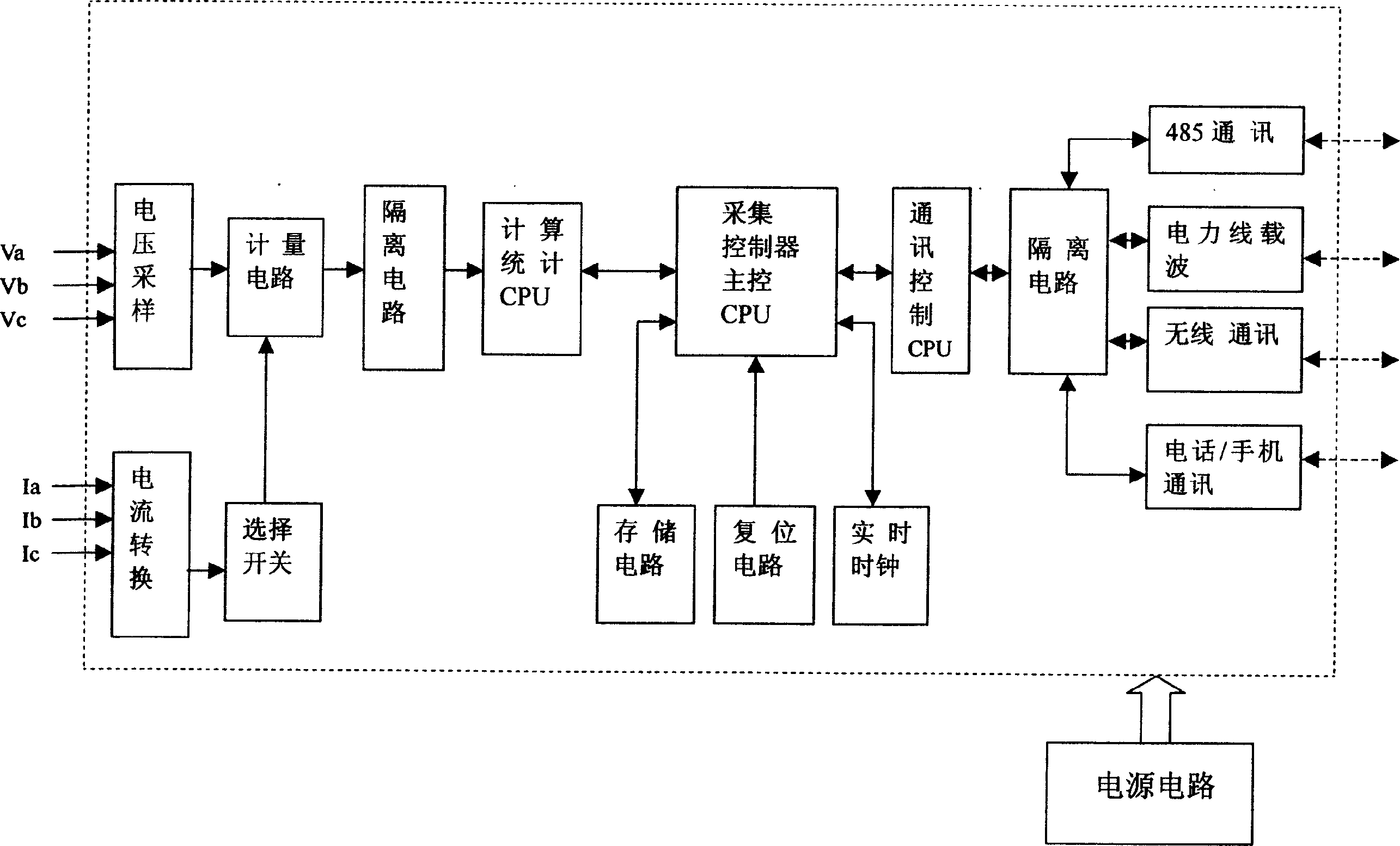
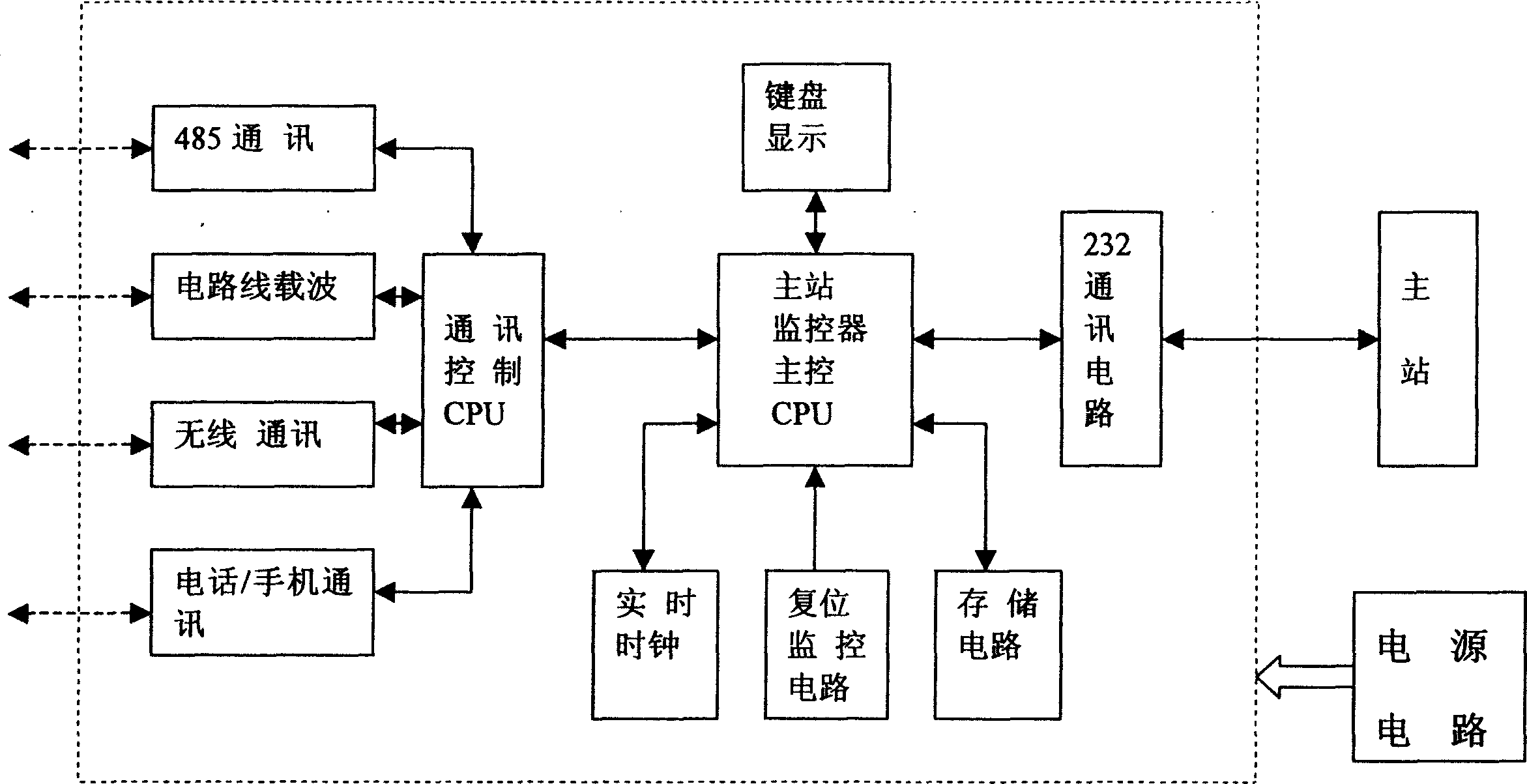
[0015] exist figure 1 In the present invention, it includes a power supply circuit, a voltage sampling circuit, a current conversion circuit, a selection switch circuit, a metering circuit, a calculation and statistics CPU, an acquisition controller main control CPU, a reset circuit, a storage circuit, a real-time circuit, a communication control CPU, and an isolation circuit and a communication device, a metering circuit, an isolation circuit, a calculation and statistics CPU, an acquisition controller main control CPU, a communication control CPU and an isolation circuit are sequentially connected between the voltage sampling circuit and the signal transceiver device, and the selection switch circuit is respectively connected to the current The conversion circuit is connected with the metering circuit, and the reset circuit, the storage circuit and the real-time circuit are respectively connected with the main control CPU of the acquisition controller; the main control CPU of...


PUM


Abstract

The device includes power circuit, voltage sample circuit, current switching circuit, selective switch circuit, measuring circuit, computing statistics CPU, main controller CPU of collection controller, reset circuit, memory circuit, real time circuit, communication control CPU, and isolation circuit etc. Characters are that following circuits are connected between the voltage sample circuit and signal transmitter receiver set: measuring circuit, isolation circuit, computing statistics CPU, main controller CPU of collection controller, communication control CPU etc. The selective switch circuit is connected to the current switching circuit and the measuring circuit. The reset circuit, memory circuit, and real time circuit are connected to main controller CPU of collection controller respectively. The invention possesses features of simple structure, stable operation, and easy of use. The device provides favorable condition for managing equipment of power distribution scientifically.

Description

technical field [0001] The invention belongs to the technical field of electric power equipment, and in particular relates to a device capable of realizing remote monitoring and distribution of power. Background technique [0002] In the existing technology, the power distribution equipment used by enterprises is regularly maintained and inspected by professionals. Once the power distribution equipment breaks down, it takes a long time for the maintenance personnel to find the fault and repair it; There is no automatic monitoring device on the power distribution equipment, so it is impossible to accurately and timely grasp the operation status of the power distribution equipment, and it is difficult for enterprises to realize scientific management of the power distribution equipment. Normal use. Contents of the invention [0003] The purpose of the present invention is to provide a remote monitoring power distribution device with simple structure, stable operation and con...

Claims


Application Information

Patent Timeline
Patent Type & Authority Applications(China)
IPC IPC(8): H02J13/00
Inventor 郑结明胡国攀王庆山
Owner 赵勤彪
Learn More