
Compound controlling hydraulic system of blank turnover machine

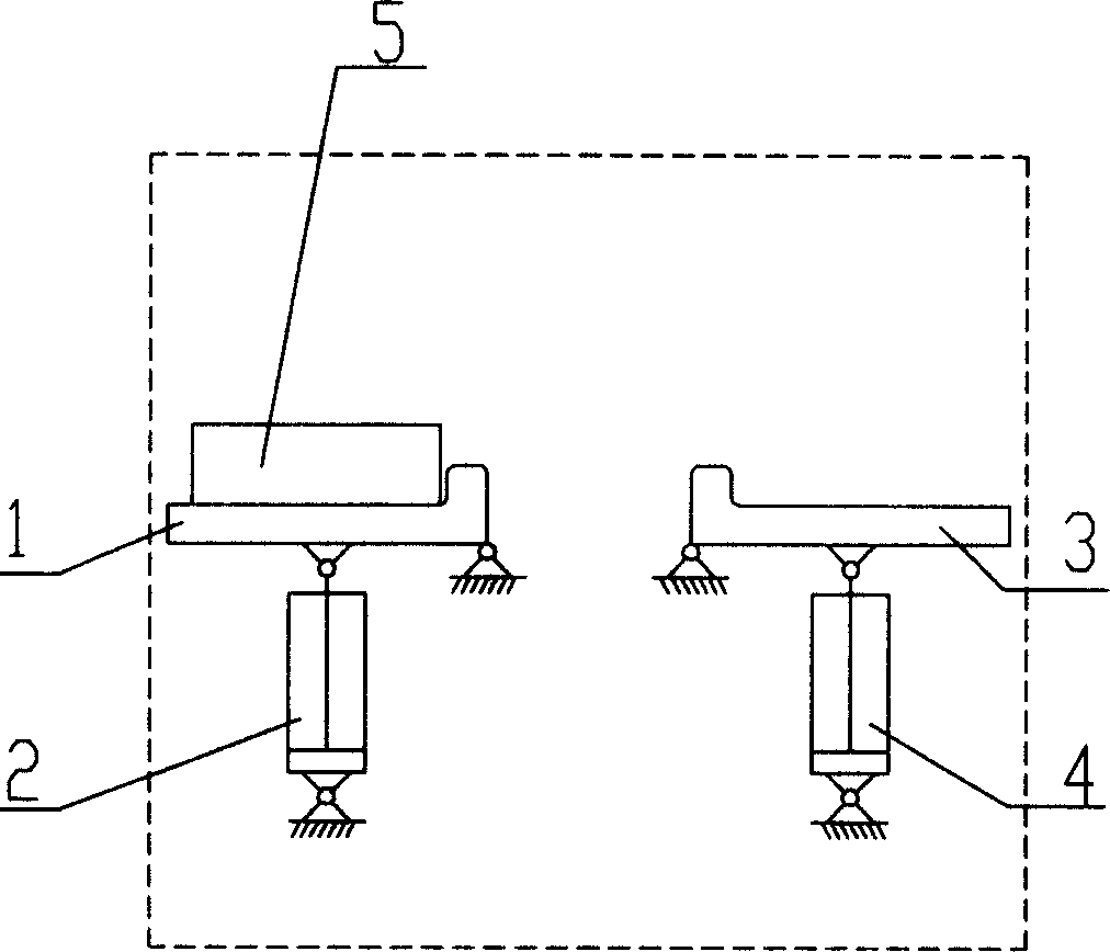
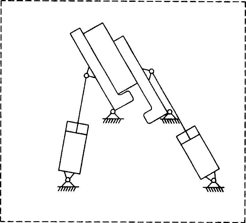
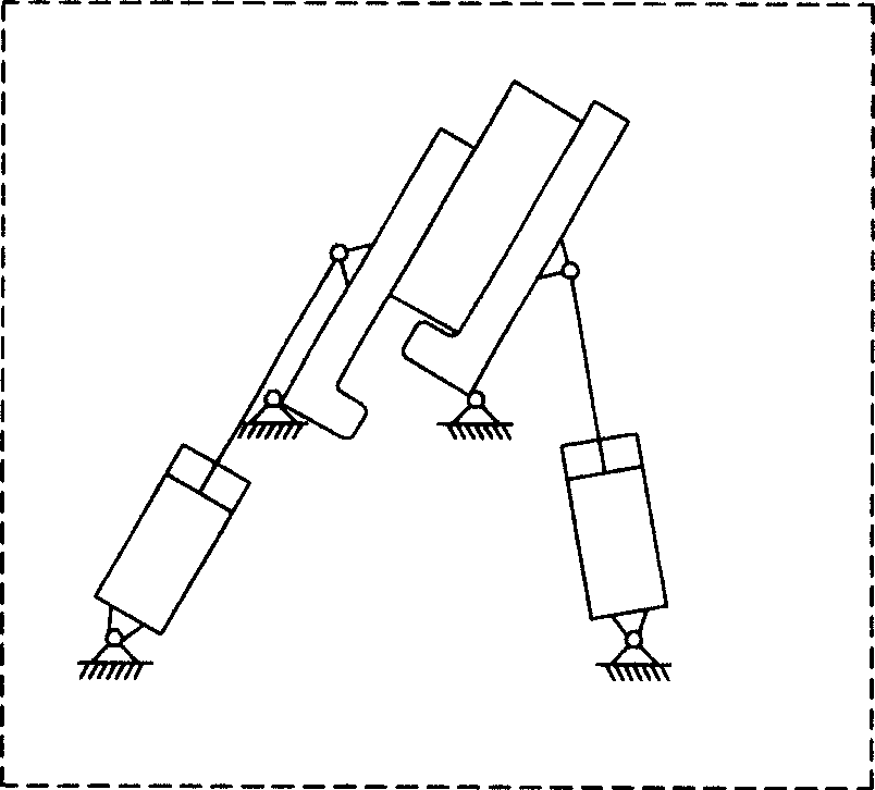
A composite control and hydraulic system technology, applied in the field of hydraulic system equipment, can solve the problems of large reversing impact, high operating cost and low service life.

Inactive Publication Date: 2006-01-11
CHINA NAT HEAVY MACHINERY RES INSTCO
View PDF0 Cites 6 Cited by
  • Summary
  • Abstract
  • Description
  • Claims
  • Application Information

AI Technical Summary

Problems solved by technology

[0002] There are two types of existing turning machine control hydraulic system equipment: one is to use electromagnetic reversing valve and logic valve to control the direction of each turning arm of the turning machine, and the speed regulating valve to synchronize the turning arms of the turning machine control, the control hydraulic system of this turning machine has a large reversing impact, the pipeline is easy to burst, and the system reliability is poor
The second is to use a hydraulic synchronous motor to synchronously control the turning arms of the turning machine. In this way, because the expensive synchronous motor is always in operation during work, the internal components wear each other, the synchronization performance cannot be adjusted, and the service life is low. , high operating cost

Method used


Image

  • Compound controlling hydraulic system of blank turnover machine
  • Compound controlling hydraulic system of blank turnover machine
  • Compound controlling hydraulic system of blank turnover machine

Examples


Embodiment Construction

[0013] Example Figure 5 As shown, the pressure oil end of each of the four drive cylinders 2 connected to the left arms L of the blank turning machine is respectively connected to a speed regulating device, and the speed regulating device is composed of a speed regulating valve The rectifying plates 4-1~4-4 form a bridge structure with the speed control valves 3-1~3-4 respectively, so that the piston rods of the four hydraulic cylinders are extended and retracted, and the piston rods of the four hydraulic cylinders are extended and retracted synchronously. The speed regulating valve 3-1~3-4 is controlled; the input control end of the speed regulating device and the left arm L are composed of the speed regulating valve rectifying plate 4-1~4-4 and the speed regulating valve 3-1~3-4 respectively. The output end of the first balance valve 2-1 controlled by the oil circuit is connected, and the input end of the 2-1 balance valve is connected to the A end of the proportional elect...


PUM


Abstract

A hydraulic system for the complex control of billet turning-over machine is composed of left arm unit and right arm unit. Each of left and right arm units is composed of 4 drive cylinders, 4 speed regulators for said drive cylinders, the first balance valve, proportional electromagnetic diverter valve, the second balance valve and overflow valve. Their connection scheme is also disclosed.

Description

technical field [0001] The invention relates to a hydraulic system equipment, in particular to a composite control hydraulic system of a billet turning machine. Background technique [0002] There are two types of existing turning machine control hydraulic system equipment: one is to use electromagnetic reversing valve and logic valve to control the direction of each turning arm of the turning machine, and the speed regulating valve to synchronize the turning arms of the turning machine Control, the control hydraulic system of this turning machine has a large reversing impact, the pipeline is easy to burst, and the system reliability is poor. The second is to use a hydraulic synchronous motor to synchronously control the turning arms of the turning machine. In this way, because the expensive synchronous motor is always in operation during work, the internal components wear each other, the synchronization performance cannot be adjusted, and the service life ...

Claims


Application Information

Patent Timeline
Patent Type & Authority Applications(China)
IPC IPC(8): B21B39/20
Inventor 郭星良艾春璇
Owner CHINA NAT HEAVY MACHINERY RES INSTCO
Learn More